

Hydraulic gear pumps are essential in different industrial and mobile uses as they allow hydraulic fluid to be transferred for work. Awareness on the operations of these pumps is critical to people engaged in machine maintenance or design since what they do affects how systems work. This paper looks at the basic principles that make up hydraulic gears; this involves the creation process, mechanics of fluid motion, and why it is better than other types of pumps. In the end, readers should have an improved understanding of hydraulic gear pumps’ functions within hydraulics systems.
What is a Hydraulic Gear Pump?
A hydraulic gear pump is a positive displacement pump that employs gears to transmit power from one location to another. It features two principal gears — an impeller and a driven gear — which revolve inside the housing and create a pressure difference that brings liquid into the pump and expels it out again. Such pumps are popular because they have simple constructions, can be relied upon and maintain constant flow rates. They work with different kinds of fluids, mostly serving as part of hydraulic systems used for driving machinery in industries like building, manufacturing or automotive production among others. Hydraulic gear pumps come in many sizes and forms, so they can be utilized for various purposes while ensuring effective fluid transfer and system pressure maintenance.
Definition and Basic Function of Hydraulic Gear Pumps
Positive displacement pumps that transfer hydraulic fluid by interlocking gears are known as hydraulic gear pumps. These gadgets create a pressure differential, which enables the suction and discharge of fluid. A casing accommodates the drive gear and the driven gear, two main parts that operate in concert to rotate the gears, causing them to draw liquid into them while propelling it forcefully out under pressure.
Technical Specifications:
- Flow Rate: This refers to how much fluid a pump can move and is measured in gallons per minute (GPM) or litres per minute (LPM).
- Pressure Rating: Hydraulic gear pumps are designed to work within different pressure ranges, typically from 1000 PSI (68.9 bar) to 3000 PSI (206.8 bar), depending on their applications and designs.
- Viscosity: The viscosity of hydraulic fluids used is usually between 32 and 46 cSt at operating temperature; this affects the efficiency and performance of these machines.
- Size and Configuration: There are various sizes & types available for different uses ranging from small handheld devices up to large industrial machinery
- Efficiency: Normally, volumetric efficiencies range from about 85% to 95%, which shows how well a pump converts input power into hydraulic power.
These parameters not only impact on the performance of a hydraulic gear pump but also determine its overall efficiency and functionality to serving any particular hydraulic system. It, therefore, becomes necessary to appreciate such aspects so that one may be able to choose and apply appropriate hydraulic gear pumps across various industries.
The Role of Gear Pumps in Hydraulic Systems
Hydraulic gear pumps depend on the efficiency and reliability of hydraulic systems in many industries. These types of pumps convert mechanical energy into fluid power, which is necessary for construction equipment and other machinery used in manufacturing. This component affects various parameters and can determine the performance of a hydraulic system.
Key Technical Parameters and Their Justification:
- Flow Rate: Another name for a pump’s flow rate (GPM or LPM) is its capacity since it shows how much liquid passes through an object over time. This is important because the faster hydraulic parts are actuated with more fluid moving around them, the quicker they respond.
- Pressure Rating: The highest pressure that can be tolerated by any given pump under working conditions where such limit may not be exceeded so as to ensure that everything operates safely without any trouble arising from failure caused by excessive forces applied against weak points within different parts making up entire assembly known as operational pressure rating. It should also prevent unnecessary wear & tear .
- Viscosity: About hydraulic fluid, thickness refers mainly to its ability whereby some oils work better than others when temperatures fluctuate significantly; therefore, viscosity should remain constant irrespective of heat changes encountered if lubrication is going to take place as required & if at all everything shall continue running smoothly enough throughout such entire process i.e., between 32 cSt and 46 cSt.
- Size And Configuration: Gear Pumps must correspond with size plus shape requirements stated within systems specifications depending on what type has been installed onto a specific machine being used at either the same workplace or different factories across the country while dealing with diverse materials like wooden planks stacked together ready for shipment overseas. Different sizes are designed differently to handle different capacities
- Efficiency: Volumetric efficiency measures how well something converts energy into another form. It is expressed as a percentage indicating proportionate conversion levels achieved or wasted during operation stages, where percentages range from 85% to 95%. In hydraulic systems, high efficiency is always desired since it lowers operational costs while maximizing overall performance levels.
A good grasp of these parameters is necessary to ensure that hydraulic gear pumps perform optimally in various working environments.
Why Use a Hydraulic Gear Pump?
Hydraulic gear pumps are used in various industries because they are reliable, durable, and efficient. Here are some reasons why they are used and what you need to know about them:
- High Efficiency: Hydraulic gear pumps typically have volumetric efficiency of 85% to 95%, which means that less energy is wasted as heat. This helps keep down operating costs while improving system overall performance.
- Compact Design: Their lightweight and compact size make them ideal for use in tight spaces or where weight should be minimized. This type of design also makes it easy to fit in different hydraulic systems.
- Consistent Flow Rate: These machines supply a steady flow of hydraulic fluid, thus ensuring that operations continue unabated in applications such as automotive systems and machines. Furthermore, they can enable the hydraulic system to respond faster due to their ability to provide accurate flow rates.
- Versatile Applications: Hydraulic gear pumps are flexible for various uses in construction, manufacturing, and automotive industries. They work well with a variety of fluids having different viscosities.
- Durability: Hydraulic gear pumps are made of solid materials that enable them to withstand wear caused by regular use, even under extreme conditions where they may be required to operate continuously without any failures. They have been designed to not only meet but exceed high pressure ratings during operation which can range between 1000 – 3000 psi thus assuring dependability throughout their service life span.
- Simplicity in Use and Maintenance: The simplicity inherent within their designs allows easy handling during installation or when carrying out repairs on site thus reducing downtime while enhancing productivity, especially within industrial setups where time equals money every second counts towards meeting deadlines set by customers therefore leading to increased profits realized within shorter periods than would otherwise be possible if complex equipment were involved instead.
- Flexibility With System Requirements: Depending on specific needs related either size/configuration/performance; these devices can easily be customized accordingly hence becoming ideal tools for countless applications.
To sum up, hydraulic gear pumps are most commonly used due to their high efficiency, durability, and adaptability to meet the different performance levels required by various systems.
How Does a Gear Pump Work?
A positive displacement hydraulic gear pump operates where fluid is moved by meshing rotating gears. A motor-driven drive gear revolves and meshes with the driven gear, thereby creating a closed chamber between them. During the rotation of these gears, gaps between their teeth get filled with liquid; that liquid gets trapped and carried around pump casing by them successively. This movement creates a pressure change that sucks in fluid from one side of an inlet while pushing it out through an outlet on another side. Due to continuous spinning, liquid is always flowing through, thus efficiency in different hydraulic applications, so they are reliable too. Besides this fact it was designed to have low leakages hence improving performance as well as maintaining pressure stability within systems.
The Working Principle of Gear Pumps
Hydraulic gear pumps operate based on a principle of positive displacement wherein fluid movement results from gears’ action. Mainly, two gears (drive and driven) are located within a shell. The drive gear is rotated by an electric motor and this in turn meshes with the driven gear causing it also to rotate thus creating pockets that seal off as they move hydraulic liquid.
Some of the critical technical parameters for hydraulic gear pumps include:
- Flow Rate: It is usually given in gallons per minute (GPM) or litres per minute (LPM). This parameter shows how much fluid a pump can deliver. Flow rates differ with the size and speed of the pump.
- Pressure Rating: It measures pounds per square inch (PSI) or bars. This value sets the upper limit for pump pressure. Hydraulic gear pumps are commonly designed for pressures ranging between 500 PSI and more than 4000 PSI, depending on their design and application requirements.
- Viscosity Range: Gear pump efficiency may vary according to hydraulic oil’s viscosity; therefore most such devices work best where viscosity ranges from 10 to 2000 centistokes (cSt).
- Efficiency: Under normal conditions, gear pumps have efficiencies rated at between 85% – 95%. These figures are affected by various factors including pump design, operating speeds and fluid viscosities.
- Temperature Tolerance: They can work within certain temperature limits which might be -20°C to +100°C (-4°F to +212°F) so that they perform well even when subjected under different conditions.
These technical parameters will enable a user to select a suitable gear pump for his specific hydraulic application, thereby ensuring its efficiency and durability within the system.
Inlet and Outlet: Drawing and Discharging Fluid
The hydraulic gear pumps’ inlet and outlet are important for the efficiency of fluid suction and discharging. A number of technical parameters should be considered while evaluating these parts.
1. Suction (Inlet) Characteristics:
- Suction Pressure: This pressure is responsible for enabling or disabling the pump to suck up liquid. If this pressure is low, cavitation may occur, interfering with how well a pump works. It is recommended that there is a minimum inlet pressure of 5-10 PSI in most cases where gear pumps are used.
- Inlet Port Size: The larger the diameter size of an inlet port, the higher its flow rate will be affected. When considering performance it would be better if there were less restrictions so bigger sizes can allow faster intake rates by reducing resistance.
2. Discharge (Outlet) Characteristics:
- Discharge Pressure: This should always match the system’s needs. A high discharge pressure shows that there’s resistance within the system, while too low pressures mean inefficient or inadequate flow rates.
- Outlet Port Size: For easy fluid delivery without back pressure, just as in case of an inlet; design this component adequately enough not to cause any restriction during fluid evacuation.
3. Fluid Compatibility: The type and viscosity of the hydraulic fluid being conveyed through the system dictate the choice of a pump and design considerations made on both ends—i.e., inlets and outlets themselves. Corrosiveness or particles within such fluids might require some material changes on ports, among other features.
4. Flow Path Design: The efficiency of the overall setup greatly depends on how paths have been configured at entry points vis-à-vis, exit points vis-à-vis bends between them; thus, minimizing curves along the route will enhance flow dynamics, leading to more efficient hydraulic circuitry.
To ensure optimum performance reliability, users need only consider these parameters together with their implications for achieving optimal efficiency levels within hydraulic systems.… Also, monitoring conditions like temperature and viscosity can help draw out or discharge fluid easily, thereby cementing the operational soundness of pumps further.
Role of Gear Teeth in Fluid Movement
In hydraulic systems, gear teeth are important for transferring fluid. They do this by engaging and rotating as they rub against each other to generate pressure while also facilitating the transfer of liquids.
- Fluid Dynamics: When gear teeth rub against one another, they create gaps through which fluids can enter or exit in a controlled manner. Moreover, the design geometry of these components determines the flow rate and pressure characteristics required for proper flow direction, so they must not be ignored during the optimization process aimed at achieving desirable performance levels where liquids are involved.
- Gear Ratio: The number of teeth on both driving gear (input) and driven gear (output) influences torque more than any other factor affecting speed reduction or increase within a system. Therefore, it greatly affects fluid motion since higher ratios will produce greater pressures but lower velocities which may be considered ideal under certain circumstances such as when dealing with high viscosity substances.
- Tooth Design: In fluid dynamics, tooth profiles can either be involute or helical. For example, compared to spur gears, helical ones provide better power transmission efficiency due to smoothness during the meshing action, leading to improved overall flow properties.
- Clearance and Tolerance: The clearance between gears should not be too tight or too loose; otherwise, no seal will be created, resulting in leakage. Hence, proper alignment must always exist among them to avoid such situations, which might compromise performance levels even further. Pumps work based on this principle; slippage decreases the pump’s efficiency significantly.
- Materials and Surface Treatment: Depending upon working conditions faced by machines containing hydraulics some materials would require hardening while others need coating for enhancement purposes like hardness resistance against wear during operation . The same applies where parts exposed under high pressures are made from hardened steel so that they don’t wear out efficiently thereby ensuring durability whenever necessary is achieved over time without compromising reliability whatsoever.
Considering technical parameters, namely gear ratio, tooth design, clearance, and material quality, etcetera optimizes energy loss within hydraulic systems, which are driven by gears for fluid flow control. To achieve this, therefore, a) Gear ratios need to be chosen wisely since they affect both torque and speed b) Different types of teeth profiles can be used depending on their impact on power transmission efficiency during the meshing process, among other things like overall flow characteristics improvement in fluid dynamics. c) Proper alignment must always exist between clearance tolerances so that no slipage occurs, which may lead into further leakage problems affecting pump’s performance levels negatively
Types of Hydraulic Gear Pumps
Hydraulic gear pumps can be divided into two main categories: internal gear pumps and external gear pumps.
- Internal Gear Pumps: These pumps have an inside gear that meshes with an outside gear. This design creates pockets of fluid that move through the pump. A wide range of different liquids can be used with this type because it is able to deal with them all even if they are more viscous than usual.
- External Gear Pumps: These consist of two gears mounted next to each other, with one driving the other. Their simple nature and generally high efficiency make them popular choices in many industries. They are usually suited for situations where less thick fluids need pumping and are simpler to maintain.
Further classifications for both kinds may include fixed and variable displacement options as well as different configurations like direct drive or belt drive systems among others which allow them to provide more specific solutions for various hydraulic applications where fluids must be handled differently based upon factors such as flow rates required across ranges of pressures involved etcetera
External Gear Pump and Its Characteristics
The robust design and efficiency of external gear pumps in fluid transfer are widely acknowledged. Some key features that characterise external gear pumps are:
- Simplicity of Design: They have fewer moving parts than other types of pumps, which makes them easier to produce and maintain and thus reduces operational expenses.
- Higher Efficiency: Typically, volumetric efficiency is better with external gear pumps due to the simplicity of their gears’ engagement, which causes minimal slippage between them.
- Versatility: These pumps can handle a wide variety of fluids, from low-viscosity liquids to slurries, and hence, they can be applied in different industries.
- Clean Operation: This design lowers contact between the fluid and seals or other parts thereby cutting down leakage as well as contamination.
Technical Parameters for Consideration:
- Flow Rate: The number of gallons or litres per minute (GPM or LPM) that a given pump can move within a specified time frame.
- Viscosity Range: This refers to how well this pump can accommodate different fluid viscosities, enabling easy transportation of fluids.
- Pressure Rating: pounds per square inch (PSI) measures the maximum pressure at which the pump should work comfortably.
- Speed: revolutions per minute (RPM) at which gears rotate during operation affects both flow rate and efficiency levels realized by a pump
- Material Construction: The materials employed in the pump’s structure may influence durability, compatibility with various fluids, and operational temperature range, among other things.
These parameters help identify an appropriate external gear pump for specific applications thus ensuring best performance and hydraulic system reliability.
Internal Gear Pump: How It Differs from External Gear Pumps
Distinctive design and operation are the two most notable features of internal gear pumps compared to external gear pumps. They are known for several advantages and specific technical attributes. Here is a breakdown of how they differ along with corresponding technical parameters.
- Design: The pump comprises two gears, one being the rotor (internal gear) and the other a pinion (external gear). The rotor has fewer teeth than the pinion to allow for a continuous smooth flow of fluid, which also helps create a vacuum, thus drawing fluids into the pump more effectively.
- Smoothness of Flow: A constant displacement throughout each revolution makes these devices provide regular flow rates, thereby minimizing pulsation that may interfere with the smooth transfer of liquids from one place to another. This makes them ideal for high-viscosity applications where consistency counts more than anything else.
- Viscosity Handling: Compared to external gear pumps, this type does well with higher viscosities. This is made possible by its ability to handle thicker liquids without compromising efficiency.
- Pressure Capabilities: Most internal gear pumps have greater pressure ratings, making them suitable for use under demanding conditions requiring elevated levels of pressure. Depending on design specifications, such devices can achieve up to 300 PSI or even higher pressures.
- Self-Priming: An inherent self-priming characteristic is another major advantage associated with these types because air might be present in fluid lines sometimes but not always so it still depends on other factors too like operating speed among others.
- Material Construction: Typically made from rigid materials like stainless steel or cast iron, internal gears tend to be durable enough to withstand harsh environments, including temperatures above normal range, as well as exposure to corrosive fluids during operation stages.
- Efficiency: In general, internal gears often exhibit lower efficiencies due to increased internal friction relative to externals. However, adequate efficiency levels can be maintained provided proper configuration is done right away!
- Applications: These versatile units find wide use across many industries, including chemical processing plants,lubricating systems used in factories, and food establishments.
By looking at these critical differences and parameters like flow rate, viscosity range, pressure rating, operational speed, or even material construction, you should be able to choose the most suitable gear pump for your needs, thus ensuring that everything works as expected within hydraulic systems, where reliability is paramount.
This brief review draws upon information gathered from leading industry resources such as specialized websites focusing on fluid mechanics and hydraulic equipment.
Comparison with Other Hydraulic Pumps
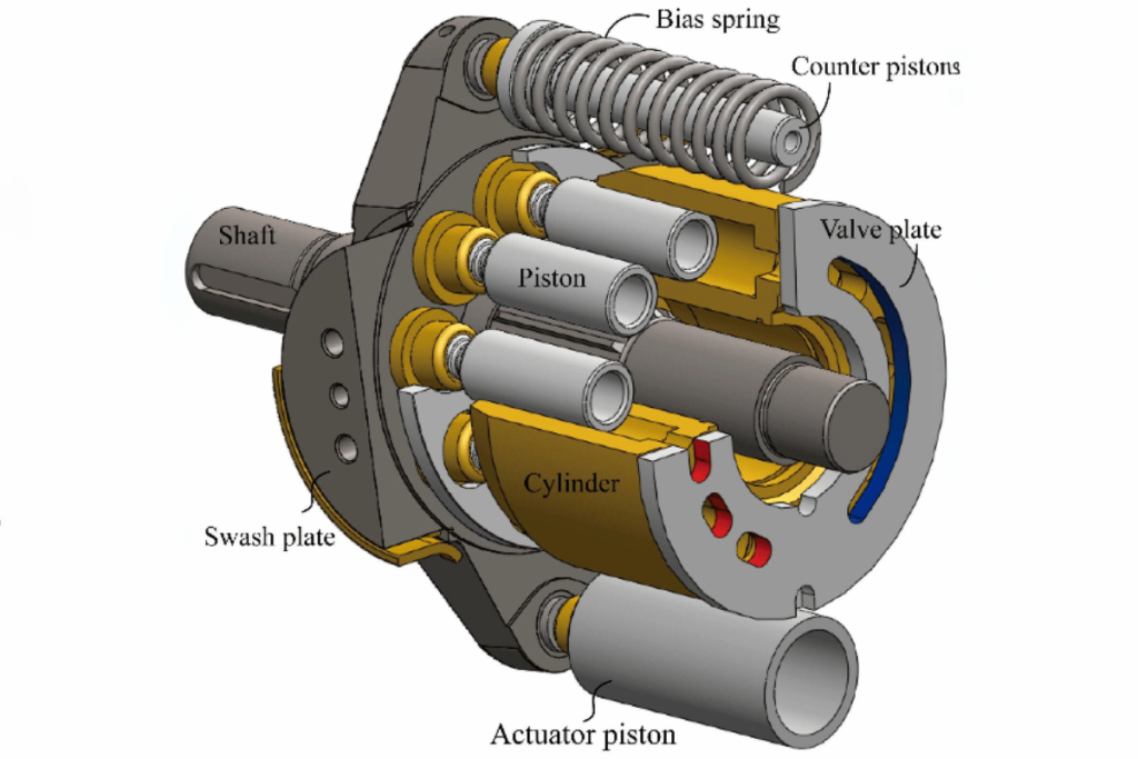
To compare with others like exterior gears, piston and screw pumps among different types of hydraulic systems, there are some critical technical parameters that must be considered.
- Rate of flow: While external gear pumps can handle large volumes because they are designed to do so, internal gear pumps generally offer lower flow rates. However, piston pumps can provide high pressure rate flows thus ideal for use in demanding applications.
- Viscosity range: Internal gear pumps can handle highly viscous liquids, making them suitable for use in lubrication systems, among other things. On the contrary, external gear pumps can work with a wider variety of fluids but may struggle with very high viscosities. Piston pumps also exhibit this versatility by efficiently accommodating different levels of viscosity.
- Pressure rating: As mentioned earlier on, these types can achieve up to 300 PSI ratings; however external varieties can reach even higher than that sometimes exceeding 400 PSI while piston ones often go beyond 5000 PSI making them good for heavy duty jobs where lots of power is needed.
- Speed of operation: These tend to rotate at lower speeds which helps in maintaining their efficiency levels whereas external counterparts can make revolutions faster but become less efficient due increased turbulence created within. Depending on what needs doing or being achieved regarding an application’s operational requirements; pistons allow for various ranges speed so that one has options.
- Construction materials: There is no much difference between these three when it comes material used since all need strong metals such as stainless steel or cast iron so they don’t break easily under intense conditions where they might be employed like those encountered by screw type involving corrosive substances.
- Effectiveness: Because leakage does not happen frequently during low pressure scenarios, inner parts may have a slight advantage over outer parts, which would then enhance overall efficiency, especially if many leaks were occurring simultaneously at high flow areas around an external gear system while still achieving similar efficiencies elsewhere in the same setup. Pistons themselves are complex devices though highly effective when subjected to situations demanding high pressures but requiring regular checks.
From this analysis of technical parameters, it is clear that one should choose a pump based on its specific application needs and operating environment while taking into account maintenance and operational costs. Therefore, full knowledge about these types is required before settling for any one since each has its own strengths and weaknesses.
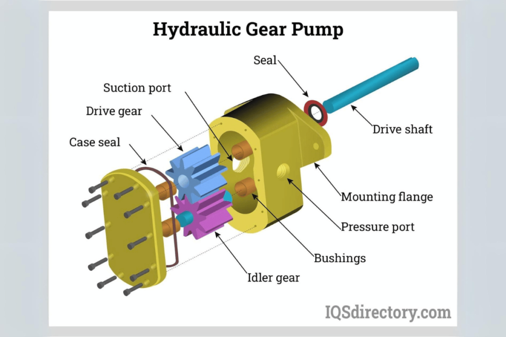
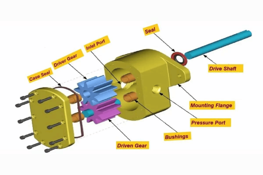
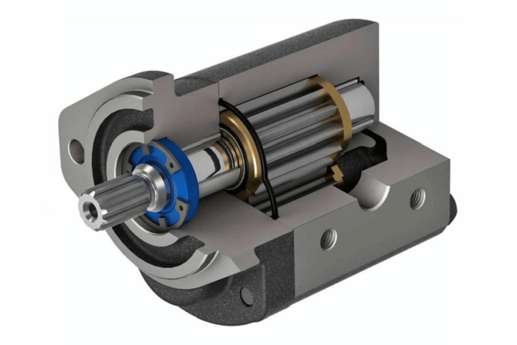
Components and Design of a Gear Pump
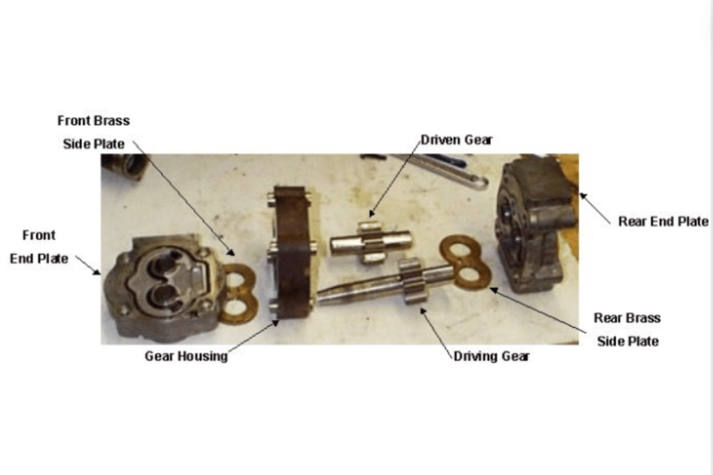
A gear pump contains gears, a housing, inlet and outlet ports and a drive mechanism. It is the gears that move the fluid primarily; they rotate to cause positive displacement. The gears are placed in the housing that supports them and ensure there is no leakage while keeping this part of the machine strong enough for operation efficiency. Inlet and outlet ports allow for an uninterrupted flow of liquid by positioning them well so as fluids can enter or leave quickly without any blockage occurring within these channels at any given time. A drive mechanism like a motor usually powers up gear rotation directly or through belts plus pulleys if need be, depending on what suits best between these two methods considering different situations such as space availability, among others too numerous mention here. Simple design coupled with exact tooth engagement makes gear pumps suitable for handling different types of fluids effectively hence becoming versatile components used in hydraulic systems.
Critical Components in a Gear Pump
- Gears: The essential components of gear pumps that create smooth movement. They can affect such parameters as flow rate, pressure capability and efficiency. Gear material and tooth profile selection typically ensures sustainability in various working conditions.
- Casing: This part encloses the gears and maintains their relative positioning. It is usually made from a material which can tolerate high pressures so as to avoid failure and ensure reliable operation.
- Inlet and Outlet Ports: These ports are strategically placed to allow fluid in and out continuously through the pump. The size of the ports may affect the flow rate and efficiency of the pump; larger ones could enable higher flow rates but also lead to turbulence.
- Drive Mechanism: The drive mechanism is responsible for starting the rotation of gears. It is mostly powered by an electric motor. The type of drive system (direct drive or belt) used affects the overall efficiency and responsiveness of the pump.
- Bearings support rotating gears while minimizing friction during operation. The nature of bearings can affect how often maintenance should be performed and pump life expectancy.
- Seals And Gaskets help maintain system integrity by preventing leakage at various points along the path. Sealing materials must be able to withstand pumping fluids’ temperature range, pressure range, etc., without being destroyed in the process.
- Pressure Relief Valve: A valve that saves both gear pumps themselves from over-pressuring and broader hydraulic systems connected with them too thus acting like a safety device for all involved parties.
- Control System: Some gear pumps are fitted with electronic or mechanical control systems designed to regulate flow rates within specific limits, ensuring they always work optimally under given conditions.
- Suction Strainer: Located at the inlet, suction strainers serve as filters that trap contaminants carried by fluids before they get into contact with any internal parts. Thus, they prevent premature wear on these surfaces, which is mainly caused by abrasive particles suspended therein.
- Fluid Reservoirs: Normally part of an entire hydraulic setup, fluid reservoirs provide steady supply of hydraulic liquids to pumps while also allowing for temperature control and degassing processes where necessary.
By carefully selecting and designing each component, engineers can ensure that gear pumps meet the necessary technical parameters for their specific applications, including operating pressure, flow rate specifications and compatibility with various fluids. The right combination of materials and designs plays a vital role in maximising efficiency as well as reducing maintenance costs.
Understanding Gear Teeth and Mesh
To gear pumps, the efficiency and performance of these gears are measured by the design as well as the interaction of their teeth and mesh. Among the parameters that must be considered are:
- Gear Tooth Profile: The design of a gear tooth affects its pump’s efficiency. Some popular types include involute and cycloidal profiles; however, most people prefer using involutes because they can be easily made and distribute loads effectively.
- Pitch Circle Diameter (PCD): This feature defines how big or small a gear is; it also shows its relationship with displacement or flow rate in pumps. Changing PCD alters volumes per revolution directly affected by fluid movement.
- Tooth Count: The number of teeth on either gear determines speed & torque transmission characteristics. Many teeth provide gentle operation but low speed while few may cause vibrations at high speeds thus reducing life span through weariness.
- Pressure Angle: It is usually between 14.5°-20°; this angle affects tooth strength plus contact ratio too. Greater values make them stronger but sliding friction increases as well.
- Backlash: There should be some clearance between interlocking cogs for free play during thermal expansion or movement allowances, which is called backlash. If not dealt with correctly, binding happens, leading to inefficiencies during operation, which also affects durability.
- Mesh Definition: Quality refers to how much one tooth engages with another when they come into contact – known as “mesh”. Good meshes distribute forces uniformly preventing premature failures due to wear.
Applying these technical considerations together with an understanding of gears’ teeth versus meshes relationship will enable an engineer to tailor-make a better-performing gear pump for any given application, thereby increasing dependability while cutting down on maintenance costs.
Design Considerations for Optimal Performance
To ensure the best performance possible when designing gear pumps, you have to consider several factors. Below are some main points taken from different reputable sources:
- Choice of Materials: The choice of gears’ materials can greatly impact their strength and resistance to wearout. Among the commonly used materials are steel, cast iron, or composite materials, which vary in terms of their load-carrying capacities and corrosion resistance properties.
- Lubrication: Proper lubrication is necessary for reducing frictional forces within gear systems, thereby extending their lifespan. This requires selecting suitable lubricants, such as oil-based ones vis-à-vis synthetic counterparts, or water-based types, depending on what will work best with them operationally over time—efficiency-wise, too.
- Temperature Management: Operational temperatures should be controlled so that these devices always operate at peak levels. Excessive heat may cause thermal expansion, leading to backlash problems and gear engagement failure due to poor fitting together, while cooling systems can help avoid such situations.
- Seals And Gaskets: Sealing off any possible leakage points is essential in ensuring that fluids do not mix up or get contaminated during pumping processes but rather flow through designated channels only. It depends on what kind of fluids being handled plus working conditions mostly.
- Fits Tolerances Adjustment: For manufacturing purposes, accurate dimensions need to be established between parts that come into contact one another when assembled, such as meshing teeth, also known as backlash distance. Care must be taken not to compromise performance since changes could occur caused by wear and tear and temperature fluctuations, among other things.
- Drive Systems Arrangement: Efficiency could be achieved here through proper configuration arrangement where different ratios among gears involved should checked upon for balanced speed output respectively
- Vibration Reduction Techniques (Damping): Additional features geared towards cutting down excessive vibration might add a few extra years onto life expectancy besides reliability improvement, though this tends to add complexity, thus increasing costs incurred during the design phase itself said reduction amounting to long-term savings made after installation completion followed, by operation time ahead too.
- Prototyping Trials: Prior to settling on the final draft for production use, it is always good practice to test numerous prototypes in accordance with the required specifications so that everything is aligned correctly.
Once made part of the overall process, these designations will ultimately lead to better results in function fulfillment, which then translates into higher efficiency with lower maintenance costs over time. Gear pumps thus designed following such guidelines often prove reliable even more than expected.
Applications and Advantages of Using a Hydraulic Gear Pump
Hydraulic gear pumps are popular in many industries because they are efficient and reliable for transferring fluids. Automotive systems, manufacturing machines, mobile equipment – all need a steady flow of liquids to work correctly. They can also be used as fuel pumps for lubricating or other hydraulic fluid applications. The main benefits of such types of devices are that they are compact, provide high pressure, and can work with different kinds of fluids, including viscous ones too. Moreover, their simplicity in usage and easy-serviceability make them very cheap when applied in automation or industrial processes. In addition, the ability of these mechanisms to hold constant output coupled with volumetric output accuracy enables enhanced performance within hydraulic units thus establishing themselves as indispensable components in present-day engineering solutions.
Common Uses in Various Industries
Hydraulic pumps are widely used in various industries because of their ability to control the movement of fluids with high efficiency. Here are some common uses and associated technical specifications:
- Automotive: These gear systems help enhance steering performance by allowing power steering fluid flow. Pressure ratings typically vary from 1000 psi to 4000 psi depending on the requirements of different vehicles.
- Manufacturing Machinery: In manufacturing machinery such as presses or injection molding machines, hydraulic fluid is transferred by gear pumps. These pumps usually have flow rates between 1 and 500 gallons per minute (GPM) to accommodate different production needs.
- Construction Equipment: Gear pumps ensure the proper circulation of oil within hydraulic excavators and loaders, which enable them to lift or dig things up, among other functions; operating pressures may reach as high as 5000 psi.
- Mobile Equipment: Fork lifts and agricultural machinery use these devices to drive various hydraulic systems; typical working range is between 5 – 100 GPM for essential motion control.
- Oil & Gas Sector: In this industry they are employed mainly for transportation purposes where they have to handle corrosive substances like fuel and lubricants having viscosities higher than 100 cP; API certification is often required due to its ruggedness in harsh environments.
- Aerospace: Landing gear deployment relies heavily on hydraulics driven through gears assemblies which should be able to operate under extremely high pressures reaching up-to around 3000psi while still maintaining lightweight construction designs
- Marine Applications: For winches used in anchoring systems or any other marine applications requiring corrosion-resistant materials then variable speed options would come into play here also used alongside them would be those designed specifically for saltwater operations since most do not last long if exposed directly without protection against such conditions hence why there’s need for this type too
- Food & Beverage Industry: Sanitary versions can be found doing duty when it comes down transferring viscous products such as oils or syrups within the industry. Safeguarding against contamination is of utmost importance thus operating at lower pressures usually around 30psi – 100 psi in order not to degrade quality
- Pharmaceuticals: In pharmaceutical production lines, gear pumps are used for accurate dosing purposes with tolerances that could allow flow rates as small as 0.1 GPM so as not to compromise on final product outcome
- Hydraulic Test Stands: These systems require accurate measurement while simulating hydraulic conditions during equipment validation tests so they should achieve an accuracy level of ±1% over a range between 2 – 200 GPM.
Understanding these applications and their technical requirements will enable engineers to select the most suitable hydraulic gear pump for any given industrial setting.
Advantages over Other Pump Types
Hydraulic gear pumps have many benefits over other types of pumps, which is why they are commonly used in different fields. Below are some advantages and technical parameters:
- Excellent Efficiency: One thing about gear pumps is that their volumetric efficiency is superb and can exceed 90% most of the time. They achieve this level by being designed as positive displacement machines that do not allow much energy waste when transferring fluids.
- Compactness: Gear pumps are smaller than diaphragm or peristaltic pumps. This makes them easy to fix in restricted spaces, especially in aerospace, where there are weight limitations.
- Consistent Flow Rate: The steady flow rate provided by these devices without any pulsation may save the day for disciplines such as pharmaceuticals with minute dosing requirements (0.1 GPM).
- Viscosities Tolerance: Typically, the viscosity range handled successfully by a gear pump is between 1 cP – 100cP+; thus, thinning thickening media can be processed within industries like food processing or oil refining, among others.
- Long-term durability/Reliability: Gears are made of wear-resistant materials to withstand adverse environments; they also have anti-corrosive properties and can work well even with corrosive liquids common in the oil and gas industry.
- Ease of Maintenance: Most designs feature easy-to-remove parts making them convenient during repair works thus reducing downtime required for critical activities. Such convenience becomes very vital if operational continuity must be maintained throughout specific sectors
- Variable Displacement Capability: Gear pumps can be designed so that their capacity changes depending on operational requirements, unlike fixed displacement machines, which always have constant output regardless of demand fluctuations.
Engineers and operators must choose hydraulic gear pumps based on their industrial specificity, knowledge about these benefits, and associated tech parameters.
Limitations and How to Mitigate Them
Though gear pumps have many advantages, they also have some limits. These restrictions could hamper the performance of the pump. Here are a few common ones and how to work around them:
- They do not self prime well: Gear pumps fail to self-prime most times especially at higher viscosities; this may necessitate external priming systems. In order to minimize this, operators can use foot valves or ensure that their pumps are well filled before starting up with priming system.
- Temperature sensitivity: Gear pumps are vulnerable to changes in temperature, which affects their ability to handle different viscosities. Increased temperatures destroy fluids, thereby reducing pump efficiency. Thermal insulators or heat exchangers should be used for this purpose to maintain optimum fluid temperatures throughout operation.
- Gears wear out easily: Prolonged usage combined with the abrasive nature of certain liquids causes gears to wear out, making them less efficient and shortening their life span. This problem can be solved by choosing materials having greater resistance against wear, like hardened steel or ceramics, coupled with routine checkups where necessary during service intervals.
- Flow rate cannot vary widely: Immobile displacement gear pumps always provide steady flow rates, which might not be suitable for applications requiring variable flows. Variable speed drives (VSD) can be adopted here so that the user has control over how much liquid passes through per unit time.
- Pressure limitations: Compared to other types of pumps, gear pumps operate at lower pressures, so their rating is relatively low in relation to what is sometimes needed. To handle high-pressure demands, heavy-duty models designed specifically for such conditions ought to be selected, or alternative technologies ought to be employed.
- Noise and Vibration problems: The mechanical movement involved during pumping action makes gear type devices generate lots of noise accompanied by vibrations too. Proper mounting procedures should followed strictly alongside using vibration absorbers while ensuring regular checks on all parts are carried out frequently enough until everything remains intact as expected always.
Knowing these drawbacks and compensating for them properly will enable gear pumps work at their best in different industrial applications according to engineers’ experience.
Frequently Asked Questions (FAQs)
What are the main advantages of using gear pumps?
Gear pumps are known for their reliable performance, ability to handle various viscosities, and consistent flow rates, making them suitable for various industrial applications.
Can gear pumps handle abrasive fluids?
While gear pumps can manage some abrasive fluids, selecting materials with higher wear resistance and implementing regular maintenance to minimize wear and extend pump life is crucial.
How do I determine the correct size of a gear pump for my application?
Selecting the right size involves assessing the required flow rate, pressure, and characteristics of the fluid being pumped. Consulting manufacturer specifications and guidelines can help with this decision.
What maintenance is necessary for gear pumps?
Routine maintenance should include checking for leaks, monitoring fluid levels, inspecting for wear on gears and seals, and ensuring the pump is free of debris or contaminants.
Are gear pumps suitable for high-pressure applications?
Standard gear pumps are typically rated for lower-pressure applications. For higher pressures, it’s advisable to choose heavy-duty models specifically designed for those conditions or explore other pump technologies.