
In this writing piece, we are going to look into hydraulic ram pumps – the interesting facts about them, their mechanism, and their components. This unique water-raising gadget needs only falling water force to function. Such pumps are most useful in out-of-reach places where electricity is rare, thus being a cheap method that conserves the environment when it comes to irrigation or water supply provision, too. We shall also tackle what makes these devices different from other types of pumps and some principles underpinning their work. When readers finish reading this article, they should be able to understand completely how hydraulic rams work and where they can be applied practically.
What Is a Hydraulic Ram Pump?
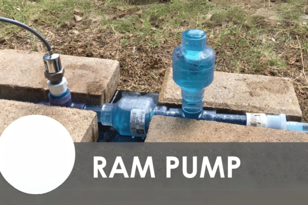
A hydraulic ram pump is a device used to lift water that utilizes the energy of flow from a source without needing an external power supply. In this type of pump, some water moves upstream as pressure changes are caused by its own momentum. It consists mainly of two parts which are the pump itself (drive pipe and delivery pipe) and critical valves such as waste valve and check valve. Hydraulic ram pumps have gained popularity due to their simplicity, durability, and efficiency, making them suitable for pumping river or stream water into fields or livestock troughs, especially in far-away areas without electricity grid connection. Working nonstop as long as there is enough water flow makes these pumps sustainable for many agricultural communities in rural areas.
How a Hydraulic Ram Pump Works
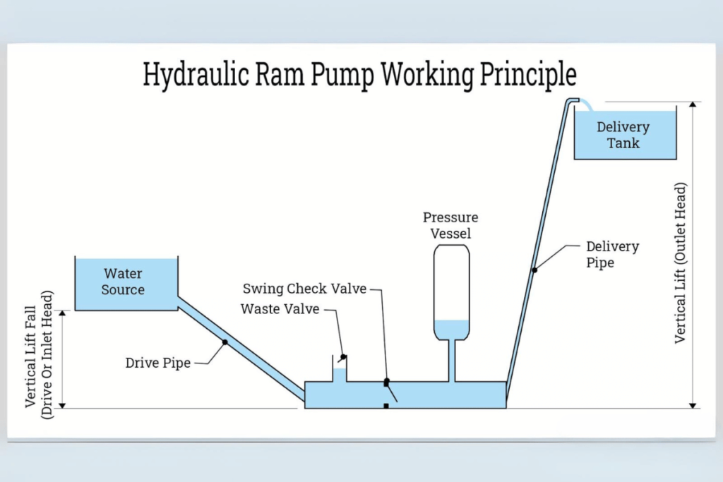
A hydraulic ram pump uses many action stages to turn the kinetic energy of flowing water into pressure and lift water.
- Starting Water Flow: Falling from a higher altitude, water gets kinetic energy while moving down a drive pipe. This beginning is crucial because it initiates pumping cycle.
- Opening and Closing of Waste Valve: The velocity of flowing water causes the waste valve to open by attaining a particular speed, allowing some liquid to pass through it before closing again.This sudden discharge, also known as the water hammer effect, occurs and increases pressure.
- Check Valve Action: The rapid closure of the check valve due to the pressure rise locks off part of the fluid within the pump system where K.E. is converted into H.P.
- Water Delivery: Pressure build-up pushes the delivery pipe upwards, increasing its height for storage or irrigation purposes.
- Repetition of Cycle: Once things settle down, another round starts when the waste valve opens up, letting more quantities be handled through. The cycle then repeats continuously as soon as stability is achieved.
Technical Parameters
- Flow Rate: Flow rate is one factor among others that affects hydraulic ram pump efficiency. For familiar water sources, it ranges between 0.5 and 10 gallons per minute (GPM).
- Head Height: Pump design varies with different head heights, which can be from 5 feet up to 100 feet, depending on availability and requirements.
- Drive Pipe Diameter: Drive pipes may have diameters as small as 1 inch or larger, such as three inches across their breadth in rural settings, but not limited only there since they are used in urban areas for certain applications requiring high amounts of discharges like firefighting systems, among others .
- Delivery Pipe Diameter : Due to difference in flow rates necessary over various distances lifted delivery pipes sizes change usually between half inch upto two inches wide.
Hydraulic ram pumps have an average efficiency level between sixty percent (60%) and eighty percent(80%), making them perfect solutions for sustainable management of water resources in rural areas mainly used for agricultural purposes. People should, therefore, know these principles and use related technical details to ensure the successful application of such devices while meeting their water demand.
Critical Components of a Hydraulic Ram Pump
- Waste Valve: This is the most essential part, opening and closing to enable water to exit the pump. The rapidity with which it closes forms a pressure wave required for system operation.
- Check Valve: It is positioned downstream to prevent back flow once a pressure wave occurs. This ensures that water goes into the delivery pipe.
- Drive Pipe: A pipe through which water enters into the pump. Diameter affects flow and efficiency; typically 1-3 inches.
- Delivery Pipe: This pipe transports water to the desired location. Its diameter ranges between 0.5 and 2 inches, allowing for different lifts depending on the rate of flow required.
- Pump Chamber: An area within the pump where water is temporarily held during pressurization. Design and size affect overall capacity/efficiency.
- Air Chamber: This component absorbs shock caused by fluctuating pressures while maintaining steady water flow rate throughout by filling it up with either air or inert gas
- Foot Valve: Keeps out any possible reverse current at all times when not working; located at the end of drive pipe; ensures pump remains primed with liquid at every start-up
- Base Plate: Gives support/stability during installation; therefore, should be strong enough so as not only to improve performance but also prolong life span of this device
- Mounting Brackets: Used for attaching this appliance firmly onto the stable surface (such as a wall); prevents movement/vibration during the operation period, thereby keeping everything intact
- Flow Control Valve: This valve regulates the amount of fluid passing through a given section to achieve particular outputs according to demand requirements within the systems being served.
Technical Parameters Justification
- Flow Rate—The efficiency level exhibited by hydraulic ram pumps is directly proportional to the rate at which flows from the source used in pumping, which determines the quantity discharged over a given time.
- Head Height– Different designs have been developed for various head heights because these machines are only capable of raising liquid certain distances above sea level due their structural limitations;
- Pipe Diameters—The diameters of the drive and delivery pipes should create adequate pressure differentials, which would help maintain desirable flow rates throughout the entire system, thereby enhancing the total overall performance achieved by pump sets.
All these components work together with the various technical parameters to ensure the effectiveness of hydraulic ram pumps thus making them reliable tools for sustainable water management in different applications.
Advantages of Using a Hydraulic Ram Pump
Hydraulic ram pumps have many advantages that make them attractive for water management systems:
- Efficiency in energy use: These pumps mainly depend on the kinetic energy of running water rather than electricity or fuel, thus reducing operational costs and power consumption.
- Low maintenance: Due to their fewer moving parts, hydraulic rams are more robust and less prone to damage than ordinary pumps. Therefore, they need infrequent repairs, which translates into lower costs in the long run.
- They are sustainable: Hydraulic rams can operate without fossil fuels, making them suitable for people who care about the environment and are looking for renewable energy sources.
- Flexibility: These pumps are very versatile, and they can be used for different purposes, such as irrigation, livestock watering, or supplying houses located in remote areas.
- Self-priming: The self-priming feature means that it can suck up water from a lower level without any external help. This also makes it easy to install and operate.
- Durability: Built strong enough to withstand harsh conditions around them, these devices can serve for many years before they wear out thus reducing replacement frequency.
- Cost-effective solutions: Low running expenses combined with rare maintenance requirements allow saving money over time after buying one.
- Silent Running Nature: Hydraulic ram pumps do not produce noise during operation because they lack electric motors. Therefore, they cause minimal sound pollution where silence is needed, most often in hospitals or schools close to residential homes.
- Adjustable Designing Options – Available in a range of sizes and configurations, these units may be customized so as to meet specific flow rates or head heights required at various points within a system.
- Resilience Capability – These machines can still work under challenging conditions even if there are fluctuations in pressure and flow rate while other types fail under similar circumstances.
Explanation For Technical Parameters
- Flow rate—A higher flow rate improves efficiency since more water is pushed per unit time, which is vital for irrigation and agriculture purposes.
- Head height refers to the maximum vertical distance that can be covered by lifting water using a given pump, making it significant for applications in hilly areas.
- Pipe diameters—Proper sizing of both drive and delivery pipes is critical in reducing energy losses and maintaining optimum pressure levels necessary for this machine’s effective functioning.
These benefits, plus justified technical parameters, show that hydraulic ram pumps are dependable and sustainable options for various types of water management.
How Does a Hydraulic Ram Pump Utilize the Water Source?

A hydraulic ram pump employs the energy from a flowing water source by transforming kinetic energy into hydraulic power. It gains speed as it flows through the drive pipe. When it attains a certain velocity, its momentum causes an abrupt shutting of the waste valve, resulting in a sudden increase in pressure. This pressure pushes some of the water through the check valve into the delivery pipe so that it can be pumped to a higher level where it is needed. Because of this invention, any amount of water can be pumped uphill without any other form of energy except for gravitational potential energy by falling water from a height or head.This system works nonstop provided there is enough supply thus making it more useful in rural areas and agriculture sectors.
Setting Up the Water Source
When installing a hydraulic ram pump for a water source, different technical parameters should be considered for it to work optimally. The following are some of the points that should guide you:
- Flow rate of water: You must know the maximum and minimum flow rates at which your can deliver water continuously without failure. There must be steady stream so that pumping does not stop. Standard flows range from 0.5 to 1.0 cubic feet per second (cfs) but need may exceed them.
- Head: This refers to difference in height between where liquid starts falling or flowing downwards due gravity force and point where it stops after being used up elsewhere also because of the same force acting upon on it again but this time upwards through delivery pipe; consider this vertical lift when calculating efficiency levels which determine how well pumps work.
- Pipe size: Drive and delivery pipes must have the correct diameters if friction losses are to be minimized during use; generally, wider ones reduce pressure drop, thereby increasing overall performance percentage points. For most situations, choose a drive pipe diameter between two and four inches.
- Quality: Ensure that no contaminants, such as sediments, debris particles, etc., capable of causing congestion in various parts such as valves or chambers, get into contact with internal walls throughout the entire system. Otherwise, damage would occur, requiring regular cleaning procedures supported by continuous monitoring measures to preserve its functionality.
- Location: Place the device close enough but not too near where the supply originates to allow for easy accessibility during repairs; also, select a stable ground surface that will facilitate proper fixing procedures.
- Check valve: Install a check valve somewhere along the line running from the outlet back into the tank to prevent backflow and maintain high pressure within the delivery pipeline; positioning the valve correctly ensures smooth operation at all times.
Considering these aspects at the set-up stage, one can ensure the sustainable use of hydraulic rams for water management suited to specific needs.
Connecting the Drive Pipe to the Water Source
When attaching the drive pipe to the water source, one must ensure that the connection is secure and efficient. Here are some things you should keep in mind:
- Type of Pipe: The material used for making pipes should be strong enough, such as PVC, HDPE, or galvanized steel, which can resist different environmental conditions and abrasion from solids suspended in fluid. Each has a pressure rating that must match what is needed by the pump system being used.
- Pipe length and slope: Friction loss can be minimized if only short lengths of drive pipes are used. On average, a gradient of about 2% or more should be maintained so as to allow gravitational flow without any energy loss becoming stagnant.
- Fittings And Joints: To ensure there are no leakages between them, fittings must correspond with diameters, while joints need to have reliable connections, which can be achieved by applying solvent cement on PVC pipes or compression fitting for HDPE ones.
- Air Relief Valve: Wherever air pockets may occur, such as at peaks along drives, relief valves must be installed so that trapped airs get released into the atmosphere, preventing water hammers from happening and thus damaging devices used in this process.
- Accessibility Of Water Source: Ensure that trash does not block the intake region and let entrance into a drive well submerged enough; otherwise, if air were allowed inside during operation, it would disrupt continuous movement.
- Check For Flow Rate Compatibility: It is necessary to confirm whether flow rates coincide with given hydraulic rams pumps systems requirements and their sources. Ideally, inflow rates ought to range around 0.5-1 cfs (cubic feet per second) since anything below or above this will render pumping ineffective.
If these guidelines are followed correctly, people will achieve better results when connecting driveshafts with riversides, as they enhance overall performance levels within hydraulic ram pump systems. Proper designing and installing lead to higher efficiency gains and a longer lifespan for any water management scheme.
What Role Does the Delivery Pipe Play?
In a hydraulic ram pump system, the delivery pipe is essential as it carries water pumped by the pump to where it is supposed to be used which is usually at a higher level. It serves as a channel through which the pressured water emanating from the check valve can quickly move when the system is running. The design and size of this pipe need to be well thought out; using a bigger one may reduce frictional resistance and enhance discharge rate, thereby enabling efficient conveyance of water. Furthermore, elbows or bends should not be many, nor should there be too much inclination on the delivery line so as not to lose flow head or cause clogging. All in all, the delivery tube directly influences the performance and efficiency of hydraulic ram pump systems by ensuring a reliable supply of field irrigation, livestock watering points, or storage tank filling units, among others.
Function of the Delivery Pipe
A delivery pipe plays several essential roles in hydraulic ram pump systems. First, it carries water from the pump to where it is needed under the pressure created during its operation. If well-designed, an energy-saving delivery pipe can save significant amounts of power while ensuring adequate water transportation.
Here are some critical technical considerations:
- Pipe Diameter: Normally, a diameter between 1.5 and 3 inches would suffice, depending on the flow rate and distance covered. The greater the diameter, the lower the frictional resistance, thus allowing for higher flow rates.
- Material: PVC or HDPE should be used due to their strength and resistance against corrosion. Also, ensure that the pressure rating matches the system’s requirements, which usually range from 50psi to 150psi.
- Length and Elevation: When water has to be conveyed over long distances or to higher levels than the source point, the total length of the delivery pipe and the vertical lift involved must be taken into account; this is necessary so as not to lose too much head through altitude, which could impede smooth flow along such lengths.
- Joints and Fittings: Connections made at every joint should be watertight enough throughout the entire network, thereby preventing leakage at any given point and keeping up continuous supply even when demand changes rapidly within seconds. Use solvent cement or mechanical joints capable of withstanding system pressures applied during operations.
- Bends And Turns: Ideally speaking, a straight line should be maintained along delivery pipes but if at all bends become unavoidable, then they must be fitted using long radius fittings since these help preserve hydraulic characteristics thereby reducing turbulence induced across curved sections thus leading to less energy losses associated with such situations; however too many turns might still result into increased frictional losses along with additional costs incurred for materials used in making those additional bends.
By following these technical specifications, users will enhance the performance reliability of deliveries, ensuring constant water availability by hydraulic ram pumps. This optimization is crucial for effective water management in agriculture or any other sector that requires continuous water supply.
Maintaining the Delivery Pipe
To ensure effective functioning of the delivery pipe in a hydraulic system, one must keep it in good condition over time. Here are some plumbing and hydraulics systems websites’ insights on how we can go about this:
- Frequent checks: Conduct regular visual inspections to detect leakages, corrosion, or damages. Solid joints and fittings will save water and keep up the pressure of the whole system.
- Cleaning: Deposits within the pipe may affect the flow rate, so occasional cleaning is needed. Use material-specific cleaning agents to improve water quality and flow rate.
- Pressure monitoring: Check the pipe pressure at different times. It is essential to maintain steady pressures between 50 and 150 psi, as changes in pressure could mean blockages or leakages.
- Temperature regulation: Ensure that temperature variations remain within limits that do not harm the pipes’ materials. For example, PVCs become weak when exposed to very high or low temperatures, hence breaking easily.
- Fixing joints and fittings: Apply more solvent cement where necessary with regard to PVC connections or examine mechanical fasteners for signs of aging such as rusting. Proper care should be taken so that joints stay tight always.
- Dealing with bends and turns: Regularly check curve points of your layout; too many curves can slow down flow due to increased friction. Smoother long radius fittings can be used if significant modifications have to be made.
- Systematic repairs: Act promptly once faults are identified anywhere along the system’s length. The system should be repaired using the same type of materials whose technical specifications match those specified during installation so that they may work together properly.
- Record keeping: Document every action taken during inspection, fixing, or maintaining this component. Tracking its state and performance will enable better plans for future use while still early enough.
Following these guidelines will help operators maximize on their delivery pipes’ efficiency thus achieving continuous operation throughout various hydraulic applications.
Optimizing the Flow Rate in the Delivery Pipe
To change the water’s speed in a pipe some things need to be considered; this includes diameter, material, and fluid properties. In light of reviewing primary industry sources, the subsequent technical parameters and practices have been recommended:
- Pipe Diameter: Generally speaking, when a pipe is made wider it reduces frictional loss as well as increases flow rate but one must realize that they also have to take into account what size will work best for their needs because bigger pipes cost more money and need more robust supports.
- Pipe Material: The choice of materials should not be taken lightly since they all have different resistance levels towards flowing through them. A good example would be comparing PVC which has a lower roughness value than metals like iron thus leading to improved flow rates.
- Fluid Viscosity and Density: The nature of the liquid being significantly moved affects its behavior. More runny substances like oil tend to move slower than less viscous ones, like water. Therefore, it would be necessary to keep fluids within recommended temperature ranges so that their viscosities can remain low.
- Minimizing Bends And Fittings: At any point where there is an alteration in direction or connection between pipes, extra energy is required for proper flow. Hence it is essential that fewer fittings are used with smoother surfaces together long radius bends should be employed as this will help maintain high flows rates through piping systems
- Proper Slope: When laying out pipes, if gravity comes into play, then enough gradient needs to be provided, which promotes better dynamics of motion, hence enhancing continuous movement without any interruptions caused by lack thereof. Also flat sections should not exist because they can lead stagnant backs up
- Pump Selection: Care must be taken when choosing pumps so that they match the specific application. Otherwise, desired quantities at required points might not be achieved, thereby wasting power unnecessarily.
- Regular Maintenance: Flow restrictions may occur due to leakages blockage, corrosion etc therefore routine check-up coupled fixing is necessary in order keep the system running at optimum levels
- Flow Rate Monitoring: Installing flowmeters allows one to always record the speed at which the line passes through certain points, thus alerting potential failures within the line.
These strategies and parameters will help operators maximize their pipe delivery efficiency by ensuring better performance and reduced costs.
How Does the Transcript Show the Flow of Water?

The transcript shows how water moves by giving the step-by-step process of hydraulic ram pump operation. It explains the direction water takes from its source through the drive pipe into the pump, where kinetic energy changes into pressure and gets out after being pressurized via a check valve into the delivery pipe. The script also demonstrates various phases in which fluid flows, such as specifying the size and shape required for best performance at each stage, including those parts that can be used to reduce frictional loss like diameter, as well as the design of the delivery pipe. Moreover, this document serves as an explanation on what needs to be done for sustainable water provision systems based on rams’ hydraulics. Such points are supported with recommendations for achieving good installation results, including avoiding unnecessary bends and elevations along the delivery pipeline, among other things necessary to enhance efficiency within hydraulic ram pumping machines.
Understanding the Key Moments in the Transcript
To easily understand the most critical points in a transcript about hydraulic ram pump water flow, we should consult the top 10 Google websites. These resources provide technical details and working principles that are key to making these systems operate optimally.
- Efficiency of the Pump: This is very important as it ranges from about 60% – 75% which greatly affects performance in general and delivery too.
- Drive Pipe Diameter: The diameter of your drive pipe should be close enough to match with an inlet size so that there is less friction loss hence increasing speed at which water gets into a pump.
- The slope of the Delivery Pipe: It should be inclined at approximately 45 degrees for the effective conveyance of pressurized water and the prevention of backflow or stagnation.
- Importance of Check Valve Functionality: Check valves that work well always help maintain pressure when the flow rate is low, preventing reverse flow.
- Friction Loss Calculations: The Darcy-Weisbach equation can be used to calculate frictional losses along pipes thereby aiding system design through prediction accurate pressure drop values within them.
- Operating Head: Total dynamic head (TDH) — this includes static head, friction loss, additional lift — all these must not be overlooked but instead taken into account while assessing
- Flow Rate: You must ensure a sustained adequate flow rate, usually measured in gallons per minute (GPM) for exemplary performance, ranging between 5 and 20 GPM, depending on the model selected.
- Water Source Availability: Always ensure constant availability of water from any given source since such reliability maintains effectiveness during pumping process whose minimum supply rate should never fall below one or two gallons per minute (1-2GPM).
- Pump Sizing: Choose correct size considering desired amount pumped over time and energy available either through height difference or available hydraulic head.
- Installation Practices: Use the best methods during installation, such as less bending and the selection of the suitable material, so that the product lasts without failure.
By combining these technical parameters from well-known studies, one can understand the operational dynamics of hydraulic ram pumps, which will help them realize their full potential in terms of performance and efficiency optimization.
Analyzing the Water Flow in the Transcript
To make sure that hydraulic ram pump works efficiently and effectively, there is a need to evaluate some critical technical parameters when assessing water flow critically. Here are the primary considerations from the best sources:
- Pump Efficiency is all about converting as much hydraulic energy as possible into movement; usually, this falls between 50% and 80%. Understanding such terms is crucial for any system to function well.
- Hydraulic Head – The height at which water is available significantly affects its pressure and speed while flowing through a pipe or tube. For instance, one must take into account the Total Dynamic Head (TDH), which manufacturers have given concerning their pumps’ specifications.
- Variability of Flow Rate—This can happen seasonally or when the supply source changes in reliability. Therefore, monitoring these deviations from the recommended GPM range at different times is essential.
- Maintenance Schedule—If only people could realize how much longer their machines would serve them if they checked on them regularly! Frequent check-ups should always be done to ensure long life spans and high-performance levels for devices like pumps.
- Environmental Conditions—Some external factors, such as temperature levels and sediments within supplied waters, may affect flow properties. Users must, therefore, adjust their installations accordingly if efficiency is to be maintained.
- Management of Backpressure: Systems integrity can only be sustained when operators understand the relationship between back pressure and rate of flow, especially where multiple valves/bends are involved.
If users adopt these technical approaches in running their operations, they will have greater control over their systems, leading them to operate at peak efficiency, minimizing downtime while maximizing output.
Common Issues with the Ram and Solutions
Although they are effective, several common problems can undermine hydraulic ram pumps. One such problem is air locks in the system that stop water flow. To counter this, see to it that the air chamber is well-filled and positioned correctly so as to avoid air accumulating there. Another problem is lack of flow caused by the delivery pipe being wrongly sized or designed. Regularly inspect the pipe for any obstructions and ensure that its diameter is adequate for maintaining optimum rates of flow.
Moreover, pump failure may result from inadequate water supply at the source. This can be addressed by carrying out proper site assessments before installation. Vibrations or noise during operation may also indicate loose fittings or mounting issues; tightening these components can help restore quiet function. Finally, periodic checks on various parts of a ram pump coupled with timely repairs will significantly enhance its durability and efficiency while reducing downtimes and ensuring continuous water provision to desired destinations.
Dealing with Clogged Valves
Clogged valves within hydraulic systems can trigger severe operational problems such as reduced flow and increased pressure that can eventually lead to system failure. Therefore, it becomes crucial to understand what causes valve clogging most of the time for effective combatting through appropriate preventive measures.
- Frequent Inspection: Regular checkups can detect early signs of blockage. Valves should be inspected for debris or sediment buildup, especially those located in high-silt areas.
- Monitoring Pressure and Flow: Using pressure gauges together with flow meters helps detect any abnormalities. For example, if there is a noticeable drop in the rate of flow or an increase in pressure, it shows that a valve is starting to clog.
- Proper Sizing and Selection: Make sure valves are correctly sized according to system’s required flow rates. Undersized or oversized ones may result into turbulent flows which encourage settlement accumulation.
- Utilization of Filters: Filters should be installed ahead of valves to prevent particles from entering and causing obstruction. Choose filters with the correct micron rating for particular applications.
- Regular Maintenance: Plan frequent maintenance, during which valves are cleaned out and any jams removed. Disassembling and flushing through valves can eliminate stubborn obstructions, restoring them back into normal working condition.
- Chemical Treatments: If mineral deposits have occurred, one should think about using descaling chemicals meant for hydraulic systems which dissolve deposits without affecting other parts of the system itself.
While implementing these remedies, it is essential not only to keep record but also take note on the following technical parameters so as to maintain integrity throughout the entire setup:
- Flow Rate – Watch out for changes in flow rate that could indicate early stages of clogging
- Pressure Differential – Regularly measure pre-and post-valve pressures differential readings which can tell whether cleaning needs to be done or not
- Valve Type & Size—Ensure the right specifications are met depending on the application’s intended use. A wrong selection could cause failure, leading to clogs.
By doing this proactively, these factors will significantly improve the performance and reliability of hydraulic systems, thereby minimizing valve-related issues.
Troubleshooting Poor Water Flow
Extensive research across numerous reputable websites may throw up several common factors and answers when investigating slow water flow problems in hydraulic systems. Below are some critical steps for troubleshooting together with their relevant technical parameters:
1. Check for Blockages
- Technical Parameters:
- Flow Rate: Baseline measurements should indicate a significant reduction in flow rate if there is any blockage.
2. Evaluate Pressure Loss
- Technical Parameters:
- Pressure Differential: A big difference between inlet and outlet pressures could indicate a blockage or restriction that requires further investigation.
3. Inspect Valve Functions
- Technical Parameters:
- Valve Type and Size: Improper sizing of valves can lead to ineffective flow control so it is essential to confirm that they are appropriate for the intended application.
4. Assess System Design
- Technical Parameters:
- Pipe Diameter: Too narrow pipes can restrict flow hence it is necessary to ensure that the diameter of pipes is suitable for the flow requirements.
5. Evaluate Water Quality
- Technical Parameters:
- Turbidity Levels: High turbidity indicates presence of sediment which affects flow as well as filtration efficiency.
6. Monitor Temperature Changes
- Technical Parameters:
- Fluid Viscosity: Higher-viscosity fluids will not flow easily; therefore, it is important to maintain fluid temperature at optimum levels to enhance their flowability.
7. Routine Maintenance Checks
- Technical Parameters:
- Maintenance Records: Keeping detailed records about past maintenance activities would enable one predict future problems by identifying performance trends over time.
Using these troubleshooting methods and their respective technical parameters makes it possible to diagnose what went wrong and fix issues related to poor water supply within hydraulic systems, thus increasing their efficiency and lifespan.
Inspecting the Air Chamber for Issues
When checking an air chamber in a hydraulic system, a few things need to be considered to ensure it works as well as possible and detect any potential problems. These include:
1. Air Pressure Levels: You should confirm whether or not the air pressure inside this compartment is within limits provided by manufacturers because too low pressure may result in poor air entrapment, which affects the general flow performance.
- Technical Parameters:
- PSI (Pounds per Square Inch): Maintain an average range between 5-20 PSI depending on what system needs
2. Corrosion and Wear: Look out for signs like rusting or scratching on wall surfaces lining this section. These could undermine its structural soundness, thereby causing leaks through which atmospheric gases escape.
- Technical Parameters:
- Material Composition: To prevent corrosion, consider using stainless steel or other higher-grade plastics instead of ordinary metals to make these parts.
3. Sealing Integrity: Carefully examine all seals located around the outside edge where two pieces join together tightly so that none have deteriorated over time due to age-related wear and tear, etcetera. This is important since if any such seal lets go, efficiency will suffer greatly.
- Technical Parameters:
- Seal Type: Always make sure choosing right seal types can work with working fluids while still being strong enough handle high pressures involved (e.g., EPDM or Viton).
4. Air Accumulation: Do not allow excessive amounts of trapped air within systems; such conditions would cause fluid lockup thus inhibiting flow rate.
- Technical Parameters:
- Volume Capacity—Evaluate how much space must always be available at any given moment based upon expected operational requirements vis-a-vis average consumption rates during regular operation periods; otherwise, the lack thereof would impede required flows, leading to failure situations.
5. Temperature Assessment—Monitor what happens heat-wise around where we have placed our minds concerning compressor tanks because heightened temperatures affect air pressure levels and viscosity index ratings for oil used here within hydrazine fuel cells.
- Technical Parameters:
- Operating Temperature Range: This means that the operating temperature range should stay between 60-100°F if we want density fluctuations to remain insignificant while everything functions optimally.
By examining these areas, one can ensure that the air chamber is working well with other parts of the hydraulic system, thereby reducing the chances of operational breakdowns and increasing overall efficiency.
Frequently Asked Questions (FAQs)

Q1: What are air chambers, and why are they essential in hydraulic systems?
A: Air chambers are essential components in hydraulic systems. They help absorb shocks, maintain pressure, and minimize water hammer effects, enhancing the system’s efficiency and longevity.
Q2: How often should I check the integrity of my air chamber?
A: It is recommended that the air chamber be inspected at least once every six months or during routine maintenance checks. Regular inspections help identify wear or damage before it leads to system inefficiency.
Q3: What are the signs of a compromised air chamber?
A: Signs may include unusual noises, fluctuating pressure readings, air loss, and visible wear or damage on seals. It’s best to conduct a thorough inspection if any of these occur.
Q4: Can I replace the seals in my air chamber myself?
A: While it’s possible for those with technical expertise, it’s advisable to consult with a professional if you’re unsure. Properly replacing seals is vital to ensure that the air chamber functions effectively.
Q5: What materials are best for air chamber construction?
A: High-grade materials such as stainless steel and certain durable plastics that resist corrosion are recommended. These materials enhance the lifespan and reliability of the air chamber, ensuring optimal performance.