

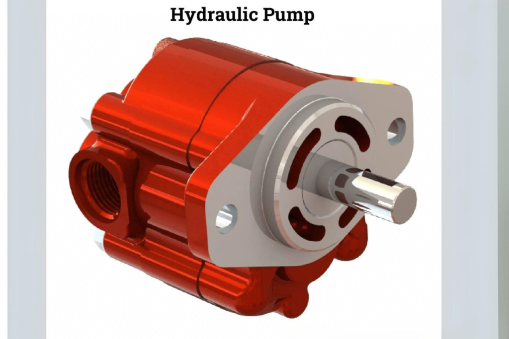
Hydraulic pumps are a vital part of many machines and systems as it helps with the effective transmission of power through liquid. In this piece, we will look at what hydraulic pumps are made up of, their functions as well as the different industries where they can be used. Appreciating how these gadgets work enables one see that they can be applied in various tasks such as lifting heavy objects or providing energy for complicated equipment among others. Whether an experienced engineer or simply curious about what makes things tick in today’s world; reading through this manual will give you great knowledge on how hydraulic pumps operate within hydraulics systems themselves.
What is a Hydraulic Pump?
The hydraulic pump is a mechanical device. It changes mechanical energy to hydraulic energy by forcing fluid through hydraulic systems. It creates a flow of pressurized fluid which can be used to do work like lifting objects or powering machinery. There are different types of hydraulic pumps, for example gear pumps, vane pumps, and piston pumps each designed for specific applications based on factors such as flow rate and pressure requirements. These machines are incredibly efficient and reliable that’s why they’re used in many industries including construction, manufacturing and automotive industry among others.
Basic Principles of a Hydraulic Pump
Hydraulic pumps depend on some basic rules that govern them for them to work well. Some of the most crucial aspects include efficiency, pressure and flow rate.
- Rate of flow: It is about the amount of liquid a pump moves within a specific time measured in gallons per minute (GPM) or liters per minute (LPM). The flow rate determines how fast an activity can be done in hydraulic systems; high rates will allow quick actuation of machinery.
- Pressure: These devices generate hydraulic pressure which helps fluids move. Pressure may be indicated in pounds per square inch (PSI) or bars. Various pressures are needed by different hydraulic applications e.g., a normal range for many systems is 1,500-3,000psi.
- Efficiency: Efficiency refers to what extent something achieves its intended purpose with minimum waste; here it means ratio between output power delivered hydraulically compared with mechanical input put into it expressed as percentage points. High efficiency saves energy while ensuring good performance ie well designed ones can have over 90% efficiencies.
- Kinds Of Pumps: There are three main types based upon their basic operational principles –
- Gear pumps: These use rotating gears which mesh together and trap fluid thereby displacing it from inlet to outlet side. They are known for their simplicity as well as reliability hence mostly preferred for low pressure applications.
- Vane pumps: Sliding vanes within a rotor create fluid flow in these types offering a good balance between performance levels achieved & ease of maintenance required.
- Piston pumps : With capability to provide high pressures along with correspondingly greater flow rates they become suitable options especially when heavy duty industrial requirements need consideration during selection process .
Understanding these principles plus parameters used would help us realize how important hydraulic pumps are in driving various machines found across industries such as automotive , construction , manufacturing among others . Each type has got benefits over others thus making it possible for one type pump being ideal than another basing on specific hydraulic requirement .
Common Hydraulic Pump Types
In terms of hydraulic pump types, there are certain technical parameters and applications that need to be considered. The following is a brief overview based on the findings of leading hydraulic engineering websites.
1.Gear Pumps
Technical Parameters:
- Flow Rate: 300 GPM maximum.
- Pressure Range: Usually up to 2,500 PSI.
- Justification: Gear pumps are efficient and reliable which makes them great for low to medium pressure applications. Simple in design so easy to maintain.
2.Vane Pumps
Technical Parameters:
- Flow Rate: 1 – 60 GPM typically.
- Pressure Range: Up to 1,500 PSI.
- Justification: Vane pumps work well across different speeds as they have better performance at variable speeds than gear pumps. Designed for smooth operation with moderate efficiency levels.
3.Piston Pumps
Technical Parameters:
- Flow Rate: 1 – 1000 GPM .
- Pressure Range: In high-pressure models can exceed 5,000 PSI.
- Justification: Piston pumps are used in industrial settings where high pressures are required most often. They offer excellent efficiency and can operate at high speeds when needed.
4.Screw Pumps
Technical Parameters:
- Flow Rate: Up to 400 GPM .
- Pressure Range: Normally below 3,000 PSI but sometimes higher depending on the model used..
- Justification: Screw pumps produce a continuous flow and can handle different fluid viscosities so have many uses especially where consistent output is required..
5.Diaphragm Pumps
Technical Parameters:
- Flow Rate: Can vary widely up to 250 GPM .
- Pressure Range : Generally below 120 PSI but can go higher depending on what it is being used for..
- Justification : These types of pumps work well with abrasive fluids or slurries due their design not allowing any contact between moving parts which reduces wear significantly..
6.Rotary Indexing Pumps
Technical Parameters:
- Flow Rate : Between 1-100 GPM .
- Pressure Range : Usually less than 500 PSI.
- Justification : This type of pump is used where precise flow rates are needed such as in automated production lines..
Knowing these typical hydraulic pump types along with their technical specifications will aid in the selection process for different hydraulic systems or applications so as to achieve optimum performance and efficiency.
Role of Hydraulic Pumps in a Hydraulic System
Hydraulic systems need hydraulic pumps for their operation; the pumps are required to move fluids as well as execute tasks by utilizing force. In order to do this, they convert mechanical energy into hydraulic energy thereby creating pressure that drives machines and equipment through a flow of pressurized liquid. The efficiency of any hydraulic pump has a direct effect on how effective the whole system will be.
1.Power Transmission:
- These types of machinery enable power to be transmitted through hydraulic fluid thereby making them work more efficiently. For example, piston pumps have high flow rates ranging from 1 GPM up to 1000 GPM and can handle pressures of about 5,000 PSI which allows strong power transfer in industrial applications where it is needed most.
2.Fluid Movement:
- The major function of these devices is moving liquids from one place to another. Screw pumps excel at producing continuous smooth flow required by systems needing constant operation due to their ability to deal with flows as high as 400 gallons per minute while sustaining pressures of even up to 3,000 pounds per square inch.
3.Force Generation:
- Hydraulic pumps provide force for actuating cylinders or other devices by use of a diaphragm that oscillates when acted upon by an external pressure source such as compressed air. Diaphragm type can deliver varying amounts of fluid at rates not exceeding 250 gallons per minute under normal circumstances i.e., below 120 pounds per square inch (PSI); thus being suitable for transferring abrasive fluids without causing much weariness on itself since it operates at low speeds most times.
4.Control & Precision:
- Rotary indexing pump works best where there is need for accurate control over flow rate like automation lines during production processes. These machines ensure precise output necessary for delicate operations because they typically operate within ranges between one gallon per minute (GPM) up-to around hundred GPM and average pressures below or equaling five hundred PSI (Pounds/square Inch).
5.System Efficiency:
- Different hydraulic pumps consume energy at different rates thus affecting overall effectiveness of systems. It is therefore important to know what each pump can do in terms of performance so as to achieve maximum efficiency while keeping the cost down which helps one realize reliable operation and cost-saving benefits from such systems.
Therefore, depending on these roles it is necessary that appropriate selection be made based on various technical parameters associated with them if at all any given hydraulic system has to remain functional across different applications while still being efficient
How Hydraulic Pumps Operate in a Hydraulic System?
Systems like this are operated by hydraulic pumps. These machines create movement of the fluid in a hydraulic system by pressuring it after drawing it from a reservoir. Mechanical energy is used to force the hydraulic fluid when activated and this mechanical energy mostly comes from an electric motor or engine. What happens next is that the pressurized fluid is forced through hoses or pipes towards actuators which may be cylinders or motors, where useful work can be done with it.
There are a few stages involved when using hydraulic pumps: creating vacuum so that fluids can be drawn into them; forcing out fluids under high pressure; directing these pressurized liquids to appropriate machine parts. The effectiveness as well as efficiency of such devices greatly affects their overall performance within any given system’s ability to respond quickly enough. By managing flow rate together with pressure for pumps, one can design systems which will operate smoothly and carry out tasks efficiently depending on what needs to be done operationally.
Hydraulic Fluid and Its Importance
Hydraulic fluid, as we know, is very important for hydraulic systems to work well. Many tasks are performed by it such as transmitting power, lubricating parts and cooling off the heat produced. Thus the choice of proper hydraulic fluid cannot be overemphasized since this will indeed have an immediate effect on how a given system functions.
Main Technical Indicators of Hydraulic Fluid:
- Viscosity: This property refers to how easily or hardly liquids can flow through objects. In order that operation occurs at different temperatures, hydraulic fluids should possess correct viscosity indexes. If viscosities are high there may be more resistance inside systems but if they become too low there shall not be enough of them for good lubrication.
- Flash point: The lowest temperature at which something can catch fire in presence of open flames. High flash points mean greater safety particularly at places where there are extreme heat conditions.
- Pour point: It is the minimum temperature below which a liquid remains pourable or flows freely. Those with lower pour points continue to function efficiently even when exposed to freezing environments thereby preventing failures in systems.
- Density: A measure of weight relative to volume occupied by any object including liquids like oil used in hydraulics systems; hence density affects heaviness as well as energy loss exhibited by them while flowing from one place into another through pipes etcetera Therefore appropriate densities guarantee adequate transfer of power without much wastage due to friction during movement along tubes.
- Thermal Stability: This shows us whether a given substance can withstand elevated temperatures without breaking down fast enough or not being able to handle them entirely. More stable ones stay longer within our hydraulic machines thus improving dependability and durability levels for these units
- Properties that help things move smoothly together without wearing out too quickly – Lubrication Properties: There must be good lubricating abilities between sliding surfaces otherwise wear rate would rapidly increase leading into failure eventually causing breakdowns altogether because of What else could lead somewhere else according to this knowledge we have so far
- Chemical Stability: It is important that fluids do not degrade easily with time otherwise they may form sludge which clogs up various parts of a system. Therefore any chemical destabilization could seriously affect efficiency within systems as well as other things like creating deposits capable of blocking flow passages thereby greatly reducing overall performance levels associated with such systems.
- Content of Water: Extra amounts of moisture in hydraulic liquid results to rusting hence reducing efficiency in terms of its ability to lubricate different elements within an assembly . Therefore low levels water should always be maintained for longer life expectancy.
Selecting correct hydraulic fluid having appropriate technical indicators can greatly improve performance, ensure dependability and decrease operation costs thus making it a critical element in design and operation of hydraulic systems.
Flow and Pressure in Hydraulic Systems
Hydraulic systems’ fundamentals are pressure and flow, as they dictate efficiency and functionality.
- Flow Rate: This refers to the volume of fluid passing through a system within a specified time period – usually measured in gallons per minute (GPM) or liters per minute (LPM). Speeding up hydraulic systems operation can be achieved by increasing the rate of flow. But it is important to balance this against pressure within the system to prevent cavitation which may result into wear beyond normal limits.
- Pressure: Pressure is measured in pounds per square inch (PSI) or bar and it represents force exerted by hydraulic fluid on its surroundings. Actuators need appropriate levels of pressure for them to work effectively among other components too. Inadequate power output occurs when there is low pressure while high pressures can cause damage or failure in systems.
- Hydraulic Power: Power (HP) = (Flow Rate × Pressure) / 1,450. By understanding how flow rates relate with pressures designers can come up with systems that do not overstress any part but still meet specific operational requirements.
- Dynamic, Static Pressure: Dynamic pressure refers to pressure developed when fluid is flowing while static one measures at rest states; both should be kept under watch so as not destabilize performance or safety.
- Pressure Drop: Friction, changes in direction/orifice size creates losses called “pressure drop” along any given piping route . Forcing tight spaces like these will increase overall efficiency because all parts receive enough energy for operation where they should have done otherwise.
To sum up this discussion about flow and pressure in hydraulic systems we need also understand technical aspects related to them if our aim is achieving best performance coupled with durability. Regular checks plus fine-tuning greatly reduces breakdowns during use thereby cutting down on maintenance costs while improving reliability throughout hydraulic operations.
Understanding Pump Inlet and Outlet
The pump inlet and outlet are main parts that affect the efficiency and operation of hydraulic systems. The term ‘inlet’ refers to the point at which the fluid enters into a pump while ‘outlet’ means where it leaves after getting pressurized. Here are some important technical parameters associated with inlets and outlets of pumps:
- Entry Pressure: This is pressure exerted by entering fluid on walls of pumps generally measured in psi or bars. It affects overall performance greatly because when there is not enough entry pressure it can lead to cavitation and excessive entry pressures may overload pump’s elements.
- Discharge Pressure: Usually expressed as PSI (pounds per square inch) or bar, this shows how much force fluid has gained as it exits pump. Keeping discharge pressure within optimum range ensures meeting system requirements without causing any damage.
- Rate Of Flow: It is influenced directly by design and application of pumps; measured either in gallons per minute (GPM) or liters per minute (LPM). Flow rate also greatly affects efficiency of a hydraulic system.
- Type Of Pump: One needs to know difference between positive displacement type and centrifugal type pumps. Positive displacement types move liquids by trapping fixed volumes then forcing them through discharges while centrifugal ones depend on rotational energy for displacing fluids.
- Size And Configuration Of Pipes: Pipe diameter connected with inlet/outlet as well as their arrangement can affect rates at which there is drop in pressure along them hence proper sizing & configuring them right is vital for best performance achievable.
- Operating Temperature: Fluid’s heat can alter its thickness thereby affecting both entrance suction ability and exit discharge capacity too. Therefore, maintaining correct temperature range is critical if one wants his/her system to be efficient enough always.
- Thickness/viscosity: Measured in centistokes (cSt), viscosity controls ease with which any given liquid flows through sections such as those used during pumping process – higher viscosities mean more resistances experienced thus lower efficiencies realized.
- Net Positive Suction Head (NPSH): This parameter must be taken into account so as to prevent cavitation. It is determined by finding difference between vapor pressure of a fluid and pressure at which it enters pump. Basically, NPSH ensures that enough liquid is available for pumping without allowing formation of vapors within a machine.
In brief, knowledge about these parameters in relation to pump inlets/outlets can facilitate creation and maintenance of hydraulic systems for better performance. Monitoring them regularly plus making necessary adjustments whenever required based on such factors could greatly enhance reliability as well efficiency throughout different hydraulic activities.
What are the Different Types of Hydraulic Pumps?
Hydraulic pumps are available in different forms that serve particular uses and meet operational requirements of various systems. The most common types are as follows:
- Gear Pumps: These devices are known as the positive displacement pumps which use gears to move hydraulic fluid from one place to another. They are simple in design, efficient in nature hence can be used for application involving high flow rates.
- Vane Pumps: Vane pump consists of a rotor with sliding vanes that create pressure by pushing against the housing as it rotates. It provides smooth flow and often found in systems where variable flow is required.
- Piston Pumps: Such pumps have cylinders and pistons which help in drawing fluid into the cylinder through an inlet valve then forcing it out through an outlet valve. They can generate high pressures thus being suitable for powerful precise applications.
- Diaphragm Pumps: These ones employ diaphragms that create a vacuum on one side of the chamber thereby moving hydraulic fluid from one area to another without contaminating it with external elements such as dust particles or oil droplets which may cause system failure if not removed properly.
- Screw Pumps: Screw pump operates by rotating screws within casing thereby producing continuous flow rate for low-viscosity liquids like water or light oils etcetera.
- Peristaltic Pumps: Peristaltic pump works when some rollers squeeze flexible tubing against rigid wall repeatedly so that liquid can move along without getting damaged since shearing forces acting upon sensitive materials do not arise during this process.
- Lobe Pumps: Lobe pumps are similar to gear pumps but instead of using gears they employ lobes which transfer fluid from one part of the system to another part effectively especially when dealing with substances having large solid content concentrations.
- Submersible Pumps: Submersible pump operates while immersed into liquid medium such as well water therefore making it useful for deep pit applications where other types would fail due their inability reach desired depths.
- Electric Pumps: Electrically driven hydraulic pump is one device that can work with different systems of this kind; hence giving operators an option on how best control such system depending on need or preference.
- Manual Pumps: Manual hydraulic pump may be operated by hand and is frequently used for small tasks or during maintenance procedures when there are no other sources available for powering up the apparatus which requires fluid transfer to take place.
Each type of pump has its own strengths which determine their selection based on factors like required pressure, flow rate and characteristics (viscosity) of pumped media.
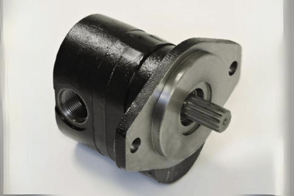
Gear Pumps: Design and Mechanism
Gear pumps are a type of positive displacement pump that increases pressure and moves fluid by meshing gears. Outer casing, driving gear, and driven gear are the main components of this pump. There are two categories of these devices: external gear pumps and internal gear pumps.
- External Gear Pumps: They involve two gears that interlock; one is powered by an engine while another is rotated by it, thereby creating cavities for drawing in liquids and discharging them.
- Internal Gear Pumps: In such systems a small rotary gear sits inside a bigger fixed one thus forming sealed chambers through which media get conveyed with better efficiency at lower speeds of operation.
Main Technical Parameters
- Flow Rate: Generally between 0.1 GPM to 500 GPM depending on pump size and application.
- Pressure Rating: Can be designed to handle up to 2500 PSI which makes it possible for them being used under high pressure situations.
- Viscosity Range: Suitable for fluids having viscosities from 1 cP up to 100000 cP i.e., covers low as well as very highly viscous substances.
- Efficiency: Often greater than 90% when conditions are favorable hence they can always deliver good results consistently.
Design features and parameters like these help engineers choose the right gear pump for a particular application so that it performs optimally in different industrial environments where reliability is required.
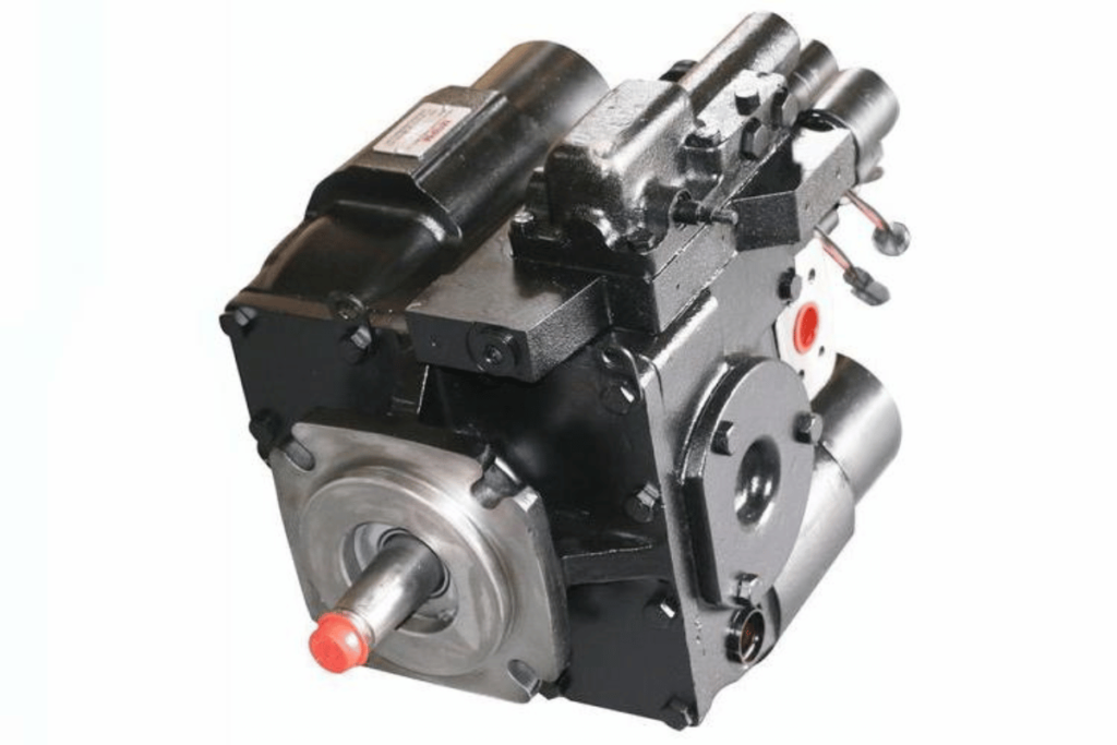
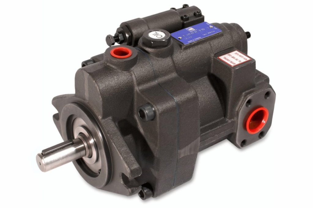
Piston Pumps: Types and Uses
Due to their ability to handle high pressures and provide accurate flow rates, piston pumps are versatile and commonly used in many industries. In these pumps, a vacuum is created by use of a piston mechanism which draws fluid into the cylinder and then forces it out through an outlet. Piston pumps have various types that include:
- Single-Acting Piston Pumps: A single stroke of the piston operates these pumps where fluid is drawn in during its downward motion and pushed out as it moves upward. They are most suitable for applications with low to moderate flow rates.
- Double-Acting Piston Pumps: With cylinders having pistons on both sides, double-acting pumps can draw in liquid during one stroke while also expelling it during another stroke hence higher efficiency and continuous flow. Such types find common usage in areas requiring large volumes of fluids pumped continuously.
- Diaphragm Pumps: These are essentially piston pumps that employ flexible diaphragms instead of rigid pistons so as to create pressure differentials necessary for handling corrosive or viscous media.
Key Technical Parameters
- Flow Rate: Pump designs and application determine the rate which can range from below 0.5 gallons per minute (GPM) up to more than 200 GPM.
- Pressure Rating: Heavy-duty industrial applications call for pumps capable of withstanding between 0 psi (pounds per square inch) all through 5,000 psi.
- Viscosity Range: Fluids having viscosity levels ranging from 1 cP (centipoise) up to 1,000,000 cP can be effectively handled; hence slurry transportation becomes possible together with other thick liquids.
- Efficiency: It normally ranges from 85% – 95% thus ensuring reliability under harsh operating conditions.
By understanding these categories alongside their associated technical parameters; engineers can select appropriate piston pumps which will maximize performance while ensuring longevity under different operational environments.
Vane Pumps: Applications and Benefits
Vane pumps are used in many different applications because they are efficient, reliable and versatile. For example, within the automotive, marine and manufacturing sectors; hydraulic systems, fluid transfer systems and lubrication systems all include vane pumps. Such fluids can be powerful machines or engines lubricants supplying abilities are made possible by their capability of handling a large number of both viscous and non-viscous fluids.
Main Technical Parameters
- Flow Rate: Vane pumps can have flow rates as low as 5 GPM or as high as over 1,500 GPM which enable them to work effectively under low or high demand situations.
- Pressure Rating: These types of pumps may operate at any pressure between 0 to 800 psi thus suiting most hydraulic applications without risk for failure.
- Viscosity Range: They handle well liquids with viscosities ranging from 1 to 100000 cP thereby making them adaptable to various industrial fluids like oils and fuels.
- Efficiency: Normally vane pump efficiencies are around 75% –89% so that significant amounts of input energy get transformed into useful work.
The selection of a vane pump should be based on the ability of meeting specific operational needs such as desired flow rates, pressure conditions and nature of handled media. In addition they have been designed for smooth running with quiet performance which makes them more attractive in environments where noise reduction is important.
How Do Different Hydraulic Pump Types Compare in Performance?
Comparing different hydraulic pump designs during selection involves a number of factors such as efficiency, suitability for use, flow rate, pressure capacity and maintenance requirements.
- Gear Pumps are sturdy and can handle high pressure which is why they are best suited for tough industrial applications. But the viscosity may cause the loss in their effectiveness.
- Piston Pumps have good energy efficiency and can be used at high pressures but are more intricate and costly due to their design.
- Vane Pumps provide uniformity in flows while still being relatively silent thus making them ideal for less demanding duties though not as effective as piston pumps under high pressures.
- Diaphragm Pumps work well with corrosive or sensitive fluids that need to be transferred without contamination although they may have lower flow rates compared to their mechanical counterparts.
- Screw pumps deliver an even amount of liquid throughout its operation especially when dealing with low viscous liquids however it might not be suitable for use with high pressure systems.
- Peristaltic pumps perform extremely well when handling shear-sensitive fluids, but they can’t match other types on efficiency to meet high volume demands.
- Lobe pumps can handle fluids with large solid contents and do so gently, however their performance changes depending on speed and what it is used for
- Submersible pumps are designed specifically for working under fluid pressure hence excel in transferring fluid from great depths but must be constantly serviced to avoid getting damaged
- Electric Pumps are versatile enough to fit various uses thanks to their ease of operation though maximum pressures achieved may not equal some alternatives.
- Manual pumps offer basic functionality at low cost especially when dealing with smaller volumes however electrical or hydraulically powered ones have more power output than them
In conclusion; one should select any given hydraulic pump type around specific needs considering desired flow rates; required pressures levels and fluid properties.
Fixed Displacement vs. Variable Displacement Pumps
Comparing fixed displacement and variable displacement pumps involves understanding their basic differences and where they are used.
1.Fixed Displacement Pumps deliver a constant flow rate with each rotation, meaning that the volume pumped is predetermined by the pump design. Generally, they have a simple structure and are easy to operate because they need steady stream rates so much of the time. Main technical parameters include:
- Flow Rate: It does not change even if the system pressure alters.
- Pressure Range: The pump design and maximum system pressure limit it .
- Efficiency: Normally higher at constant speed and flow.
2.Variable Displacement Pumps can change how fast they are pumping depending on what the system needs at any given moment; this makes them very useful for applications with varying demands such as dynamic workloads or fluctuating load levels. They use feedback mechanisms to change displacement which adds complexity over fixed types but also enhances versatility . Important technical parameters to consider are:
- Flow Adjustment Range: Variability from zero flow to maximum rating based on demand capability .
- Energy Efficiency: These types consume only as much power as required making them more efficient when loads vary
- Pressure Compensation: Capable of keeping up different pressures within a system through adjusting flow; ideal for systems with varying pressure requirements.
In conclusion, one should choose between fixed displacement pumps or variable ones depending on where he/she intends them applied. For simple high efficiency tasks fixed types would be appropriate while variable ones should be used in cases having changing flows and pressure demands.
Axial Piston vs. Radial Piston Pumps
When we compare axial piston pumps with radial piston pumps, each design has its own advantages according to applications.
Axial Piston Pumps are typified by having their pistons arranged in a line along the drive shaft. This setup allows for higher pressures and volumetric efficiency. Some of the key technical parameters include:
- Flow Rate: Because of linear motion of pistons, flow rate is generally higher at lower speeds.
- Pressure Range: Can work under higher pressures (generally up to 5,000 psi) which suits tough conditions well.
- Efficiency: Normally more efficient than radial varieties at higher speeds hence they are good for uses where performance should remain constant over time.
On the other hand, radial piston pumps have their pistons arranged around the drive shaft in a circular pattern. Torque density and compactness are some of the things that make this design advantageous. Key technical parameters include:
- Flow Rate: It can be different depending on speed and stroke length but in general it is less than that of axial types.
- Pressure Range: Works effectively within moderate pressure ranges (usually up to 3,000 psi).
- Durability: With low wear rates caused by frequent start-stop cycles during operation makes them suitable for durability.
In short words; high power or high pressure requirements would call for an axial piston pump while space limited installations together with medium range pressures may require one to use a radial type pump instead. The choice between these two types should take into account specific operational conditions as well as expected performance levels from the intended application.
Positive Displacement vs. Non-Positive Displacement Pumps
Positive displacement pumps (PDPs) and non-positive displacement pumps (NPDs) are two basic types of pumps that have different principles of operation and applications.
Positive Displacement Pumps are intended to move a defined amount of fluid per cycle without regard for pressure. Gear pumps, diaphragm pumps, and piston pumps fall into this category; they are particularly useful when it comes to handling high viscosity fluids or maintaining a steady flow rate. The main technical parameters include:
- Rate of flow: This is the capacity that ensures constant flow despite system pressure changes hence making it reliable in hydraulic systems.
- Efficiency: Where accurate flow control is required, they exhibit high levels of efficiency which improves with increase in pressure.
- Ability to self-prime: Most PDPs can self-prime effectively thus suitable for cavitating applications.
Non-Positive Displacement Pumps, on the other hand, allow energy to be transferred from the pump to the fluid which enables it move through pipes freely. These type includes centrifugal pumps as well as screw pumps often used where there are low viscosity fluids. The key technical parameters here are;
- Rate of flow: They may not be very good at maintaining steady rates because flow may vary greatly along with back pressure changes especially when operating under high pressures.
- Pressure Range: NPDs cannot handle high pressures as well as positive displacement ones but instead work better within lower ranges such volumes should also be low.
- Durability: They tend to last longer in continuous flow applications especially with clean thin liquids.
In summary, one should consider specific characteristics of a given liquid being pumped, required rate of flow, working pressure range and general design considerations for an application before choosing between positive-displacement or non-positive-displacement pump types.
Common Issues and Maintenance for Hydraulic Pumps?
While they are tough, hydraulic pumps are not without their problems. For example, they may start to leak because of worn-out seals or fittings which will result in fluid loss and decreased efficiency. Cavitation is another common issue where vapour bubbles form within the pump due to low pressure then implode causing serious damage. Overheating is also a frequent problem; this occurs after prolonged use without enough cooling or when contaminants enter the system leading to wear out of parts prematurely.
In order to maintain hydraulic pumps correctly, one should carry out regular inspections for leaks and other signs such as strange sounds or vibrations. It is important that the right amount of clean hydraulic fluid is used at all times; replacing it should be done following manufacturer’s guidelines. Furthermore monitoring pump temperature can help prevent over heating while protecting filters together with changing old seals will improve its life span too. Ultimately creating an active preventive maintenance plan greatly increases the lifespan and dependability of hydraulic pumps.
Troubleshooting Hydraulics Pumps
Below are some steps and considerations in troubleshooting hydraulic pumps:
- Detect symptoms: These could include odd sounds, decreased flow rate or overheating. This initial assessment will help guide what to do next.
- Look for Leaks: Inspect all seals, fittings and joints for signs of fluid leakage – this could mean worn-out seals or loose connections which need tightening up thereby restoring normal operations.
- Cavitation Check: Watch out for cavitation by monitoring pressure fluctuation readings along with any abnormal noise. You can prevent cavitation by ensuring there is enough inlet pressure and redesigning the system to avoid low-pressure zones.
- Temperature Monitoring: Measure hydraulic fluid temperature regularly. If it gets too hot, that could imply poor cooling or high viscosity; thus, should not exceed the limits given (usually 30°C – 60°C for most systems).
- Check Fluid Quality: Look at the state of hydraulic fluids – if they appear dirty or have changed their thickness then you know they are contaminated hence may cause other problems during operation; therefore consider replacing them after taking samples.
- Pressure Tests On The System: Confirm whether system pressures match required specifications using a pressure gauge (usually between 1500 psi -3000 psi depending on the application). Any deviation signifies pump wear and tear or blockage within systems.
- Flow Rate Test: Does the pump deliver expected rates of flow? If nozzles specify rates in GPM then make sure these are met; otherwise lower readings indicate damaged internals like gears etcetera.
- Filters/Strainers Inspection : Blocked filters restrict heat dissipation leading to performance failure due over heating.Clean this often enough so that there is always unrestricted flow of fluid through them thus maintaining optimum efficiency levels . Change whenever necessary
- Review Manufacturer Specifications : Always refer back to manual books provided by manufactures while trying to trouble shoot different faults because each type has specific tolerances when it comes down pressures , temperatures as well properties related with fluids .
- Seek Professional Help: If all else fails seek assistance from experts who specialize with these machines as they may be having more knowledge on what could have gone wrong and how best rectify it especially if one needs dismantling the pump.
Follow these steps for successful maintenance practices of hydraulic pumps. Each factor should be supported by operational need and manufacturer’s recommendation since failure to comply will lead into inefficiency of the entire system thereby increasing wear out rate.
Preventive Maintenance Tips
It is necessary to maintain hydraulic pumps in order to make them last longer and work better. These preventive maintenance tips are concise but they are based on extensive research carried out by leading industry sources:
- Regular fluid change: Hydraulic fluid should be replaced according to the recommended times – usually every 1000 hours of operation or as per manufacturer’s instructions. Make sure that the viscosity of the fluid is correct for a particular temperature of between ISO 32 and ISO 68.
- Leakage inspection: Look around seals and joints for any signs of leakage. Fixing such problems early enough will prevent loss in performance which may affect efficiency of the entire system.
- Monitoring temperature: Always check on hydraulic fluids’ operating temperatures continuously. It is advisable to keep these levels around 120°F -180°F so as to achieve desired viscosity that enhances good performance.
- Quality filters: Filters used must meet or exceed OEM specifications e.g., those rated below 10 microns; therefore, they should be replaced regularly after thorough checking also done frequently enough lest contamination creeps into components through dirty filters.
- Checks on torque & alignment: Ensure proper alignment through regular torque checks against mounting bolts hence avoiding misalignments which can cause premature wear leading additional breakdowns later on due to increased friction . Follow manufacturer’s manual guidelines while torquing
- Vibration analysis: Use accelerometers during vibrational analysis tests where unusual patterns indicate pump imbalance or wearing out / deterioration . Keep vibrations within set limits given by manufacturers since too much vibration shortens life span besides reducing efficiency.
- Monitoring seal condition: Check seals and O-rings more often than not for signs of wear out . Replace as required in order not only maintaining integrity but also preventing contaminants from entering systems thereby causing failure at some point down line .
- System pressure verification : Measure pressures periodically across systems so that you may verify if these stay between recommended ranges ( typically 1500psi – 3000psi as per manufacturer). This helps in early detection of pump performance problems .
- Scheduled Performance Testing: Create a timetable for flow rate tests where actual performances are compared against specified GPM rates with an aim of identifying any initial signs showing up as reduction in output.
- Annual professional inspection : It is important to carry out yearly inspections by qualified personnel who have experience such systems diagnosis ; this will enable them detect possible faults before they escalate into something major thus saving on time and money .
If all these precautions are taken together followed strictly according technical specifications; then undoubtedly hydraulic operators can improve their efficiency levels greatly alongside increasing lifespan pumps used .
Signs of Hydraulic Pump Failure
In order to maintain efficiency and prevent costly breakdowns, it is important to identify the signs of hydraulic pump failure early on. Some common signs are:
- Strange Noises: Grinding, whining or clattering noises may indicate mechanical wear or cavitation in the pump. Abnormal sounds should be listened for during operation as this can help detect a problem sooner.
- Reduced Output Pressure: Internal leaks or component failure could be indicated by a significant drop in pressure readings. Therefore, system pressure needs to be checked against manufacturer specifications regularly.
- Increased Vibration: According to vibration analysis excessive vibration shows imbalance or wear usually expressed in G’s (acceleration) and levels should not exceed the manufacturer’s specification.
- Overheating: Low fluid levels, inadequate cooling or excessive wear are denoted by elevated operating temperatures. It is recommended that operators compare their temperatures with standard operating range.
- Fluid Leaks: A seal degradation or loose connection may cause visible leaks around seals or fittings which indicates them being damaged. To avoid any contamination seals and O-rings should be inspected frequently.
- Inconsistent Performance: Variations within flow rates or pressure can signify potential problems either with pump itself or hydraulic circuit where it operates; hence flow rate ought to be measured in gallons per minute (GPM) against its specifications.
- Contaminated Fluid: Pump performance and lifespan can be affected by hydraulic fluid containing particulate matter or changing color; therefore filtration measures must always be used alongside regular fluid analysis.
- Failure to Start: Electrical issues such as blocked up wiring systems may result into difficulty when starting up pumps while cleaning them regularly ensures everything remains intact throughout their lifetime.
- Excessive Heat Generation: If operated at higher than normal heat levels then there might be some internal friction happening inside it which calls for immediate action otherwise this could disrupt system functionalties altogether .
- Irregular Pressure Pulsations : When there are inconsistent pulsations coming from all over then something is wrong somewhere either with the pump or the entire system hence these changes need to be monitored closely and allowable limits as recommended by manufacturers always referred to.
By closely watching out for these signs and following pressure, vibration and flow rate technical specifications, operators can effectively manage hydraulic pump performance thereby enhancing its operational life.
Frequently Asked Questions (FAQs)
- What should I do if I notice unusual vibrations in my hydraulic pump?
Unusual vibrations can indicate misalignment, wear, or other mechanical issues. It’s important to stop the pump and conduct a thorough inspection to identify the cause and prevent further damage.
- How often should I check hydraulic fluid levels?
Hydraulic fluid levels should be checked regularly, ideally before each shift or operation. However, specific schedules may vary based on the application and manufacturer’s recommendations.
- What are the common causes of hydraulic fluid contamination?
Common causes of hydraulic fluid contamination include dirt and dust entry, wear debris from internal components, moisture, and improper handling during fluid changes. Implementing proper filtration systems and adhering to maintenance protocols can help minimize these risks.
- How can I tell if my hydraulic pump needs to be replaced?
Signs that may indicate a need for pump replacement include consistent erratic performance, excessive noise, persistent overheating, and visible physical damage. If repairs do not resolve these issues, replacement may be necessary.
- What maintenance steps can I take to prolong the lifespan of my hydraulic pump?
Regular maintenance steps include monitoring fluid levels and cleanliness, performing routine inspections for leaks and wear, ensuring electrical components function correctly, and maintaining proper operating temperatures. Following the manufacturer’s maintenance schedule is also crucial.