Monthly Archives: July 2024

how a hydraulic gear pump works

How Does a Hydraulic Gear Pump Work? Understanding the Mechanics of Gear Pumps

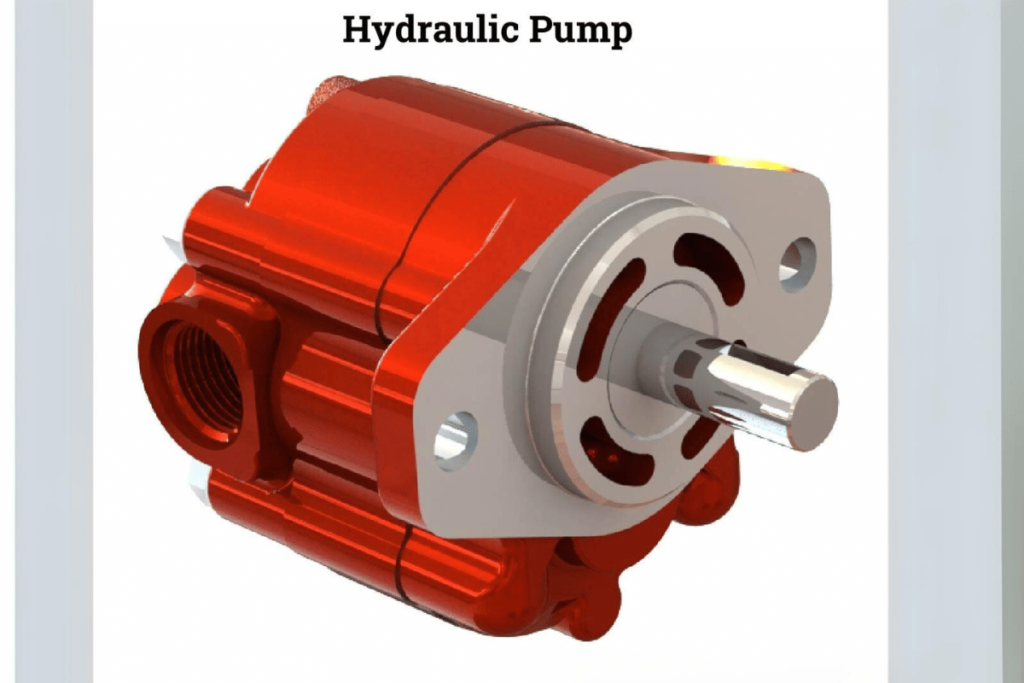
Hydraulic equipment pumps are essential in many industries and act as a practical means of transferring hydraulic fluid. In this article on gear pumps, we will examine their operational principles, principal parts, and typical uses to cover everything about them. Appreciating the way hydraulic gear pumps work exposes you to their pros and cons, thus increasing your understanding of hydraulics. This investigation will give beginners ideas and hands-on skills concerning the technology of gear pumps, whether one is an experienced engineer or just a student who wants more information about this subject.

What is a Hydraulic Gear Pump?

how a hydraulic gear pump works

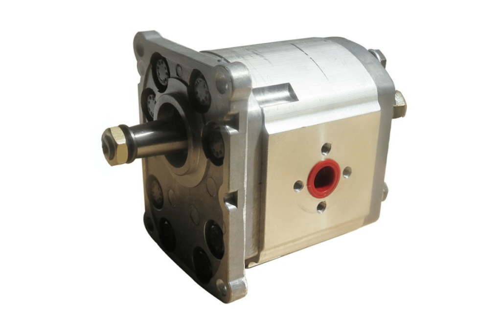
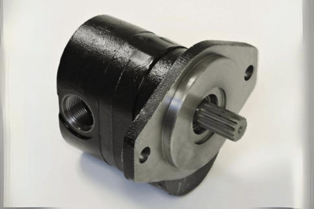
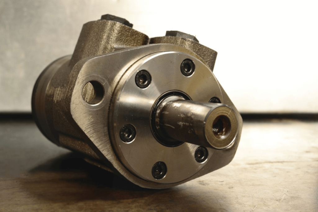
A hydraulic gear pump is a positive displacement pump that uses gears to move hydraulic fluid. Such pumps comprise two or more meshed gears that create a closed chamber, where one fluid is drawn in, and another gets displaced as these gears rotate. These types of pumps are straightforward and reliable while producing high pressure effectively. They can be seen mostly on mobile equipments like manufacturing machines etc., but also find usage within systems such as fluid power systems too. It should deliver uniform flow rates, usually over wide viscosity ranges, since it must handle different liquids commonly encountered in various industrial applications. Their robust design, coupled with operational efficiency, ensures that they are used widely across the board for most hydraulic needs, thereby guaranteeing the smooth transfer of fluids, which is necessary for completing tasks in this field.

Introduction to Hydraulic Gear Pumps

There are several points through which one can comprehend hydraulic gear pumps. Some of them include how they operate, their technical parameters, and application areas. Here’s a quick summary from various industry websites:

1. Operational Principles: Hydraulic gear pumps work on positive displacement, where two or more gears mesh together to draw fluid into a chamber and expel it. The vacuum created by rotating these gears allows the hydraulic liquid in a while pushing out displaced liquids.

2. Technical Parameters:

  • Flow Rate: Usually between 1 – 500 gallons per minute (GPM) depending on pump size/design.
  • Pressure Rating: Typically designed for pressures up to 3000 psi, some models can handle higher pressures.
  • Efficiency: Normally, hydraulic gear pumps run at efficiencies ranging from 85% – 95% meaning that very little energy is lost during operation
  • Viscosity Range: They can handle fluids with viscosities between 10 – 1500 centistokes (cSt), making them versatile for different applications.

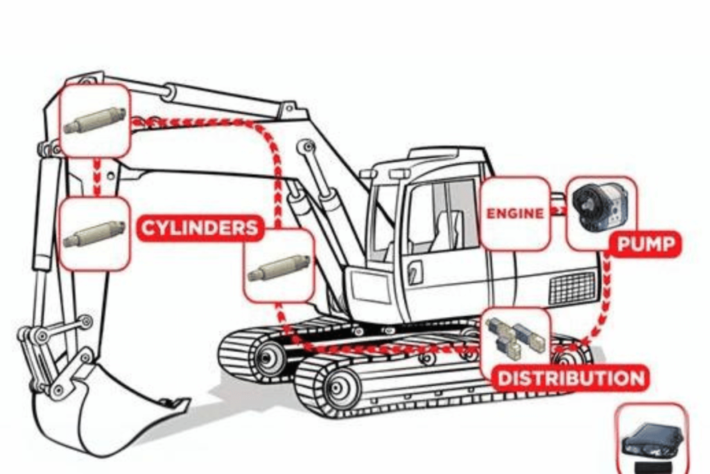
3. Common Applications: Known for their strength and ability to handle hydraulic power well, these types of pumps find wide use in construction (hydraulic excavators), the automotive industry (transmissions), and the manufacturing sector (CNC machines).

These are the basics upon which an individual can start understanding hydraulics gear pumps since, from this level, one may delve deeper into their specific roles within hydraulic systems.

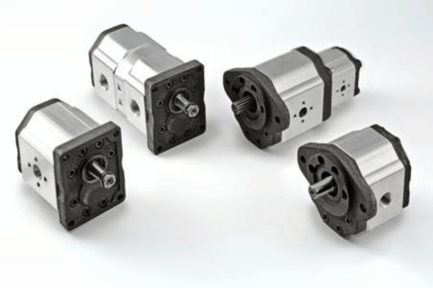
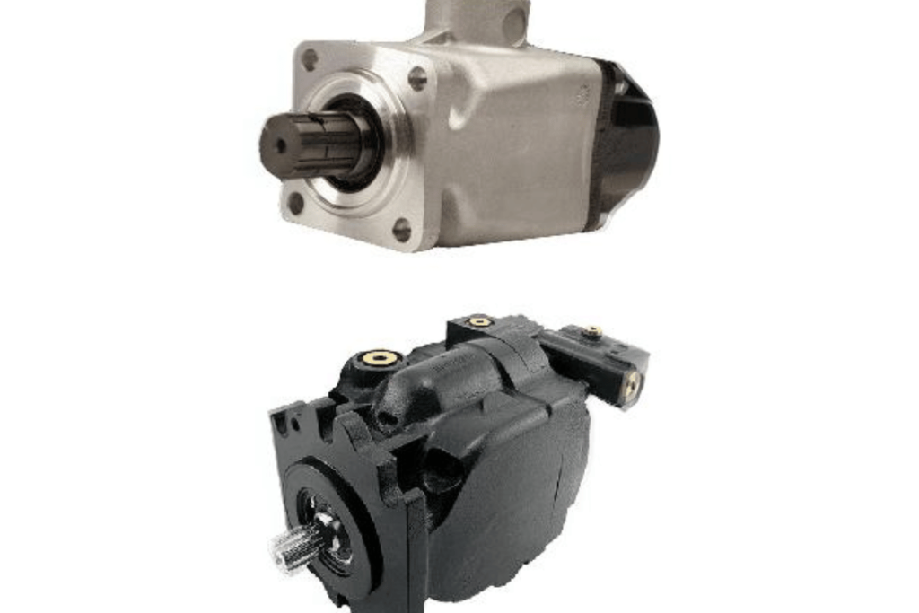
Types of Gear Pumps: Internal and External

Gear pumps can be classified into two main types: internal gear pumps and external gear pumps. They have different applications and unique features.

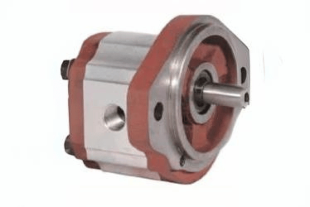
1. Internal Gear Pumps: A rotor and an idler working inside one casing. The rotor is eccentrically positioned, creating crescent spaces for fluid movement. Internal gears are famous for their ability to handle various viscosities while delivering an almost constant flow with slight pulsation. Usually, they work best at high pressures which makes them suitable for automotive and chemical industries among others where high pressure performance is required.

  • Flow Rate: 1 GPM – 200 GPM (Dependent on Size & Application)
  • Pressure Rating: Can Withstand Pressures up to 2500 PSI
  • Efficiency: Typically Attains between 80% – 90%
  • Viscosity Range: Suitable for fluids with viscosities from 30 cSt – 1200 cSt.

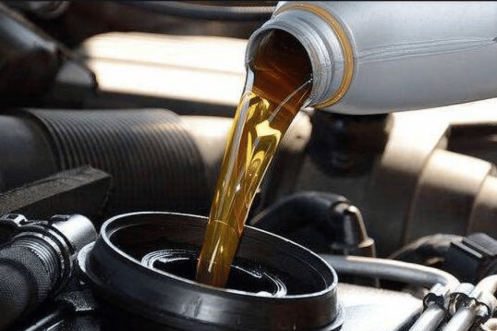
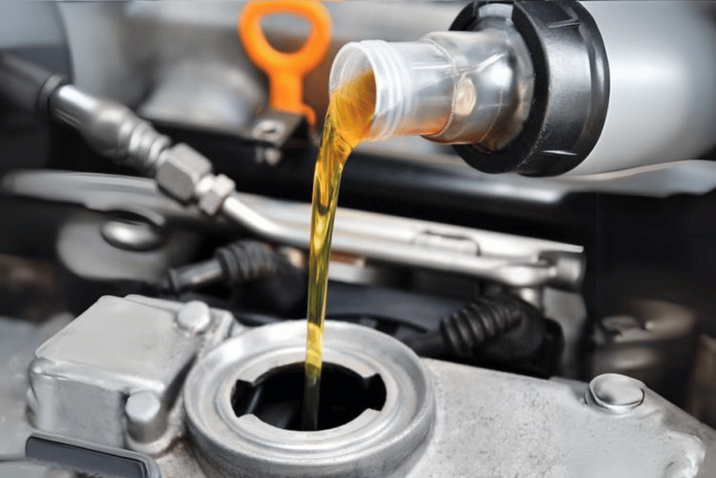
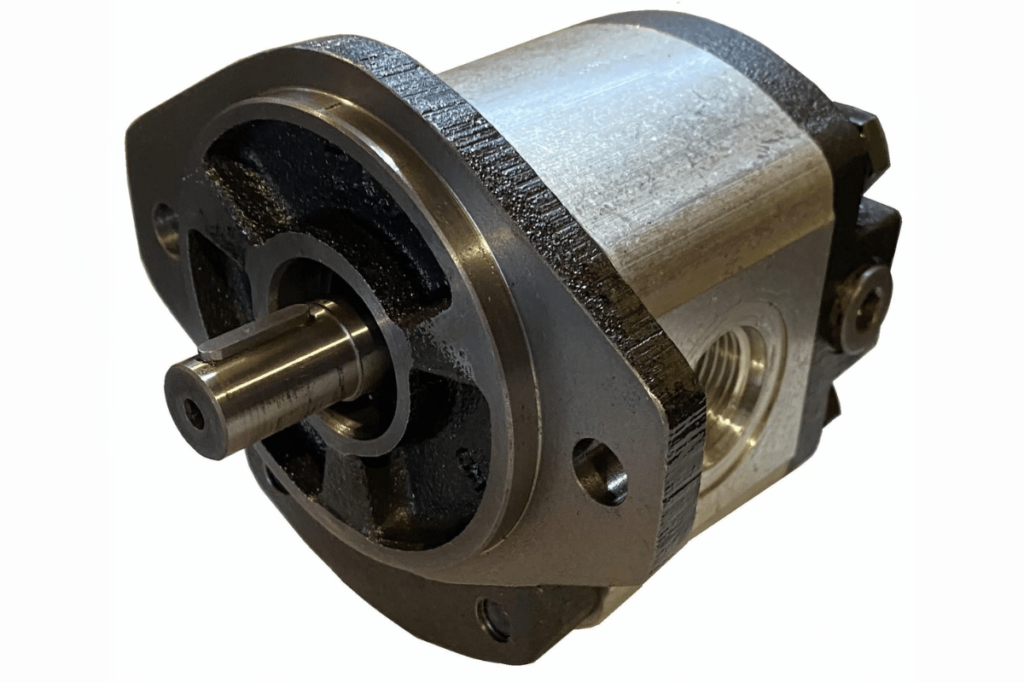
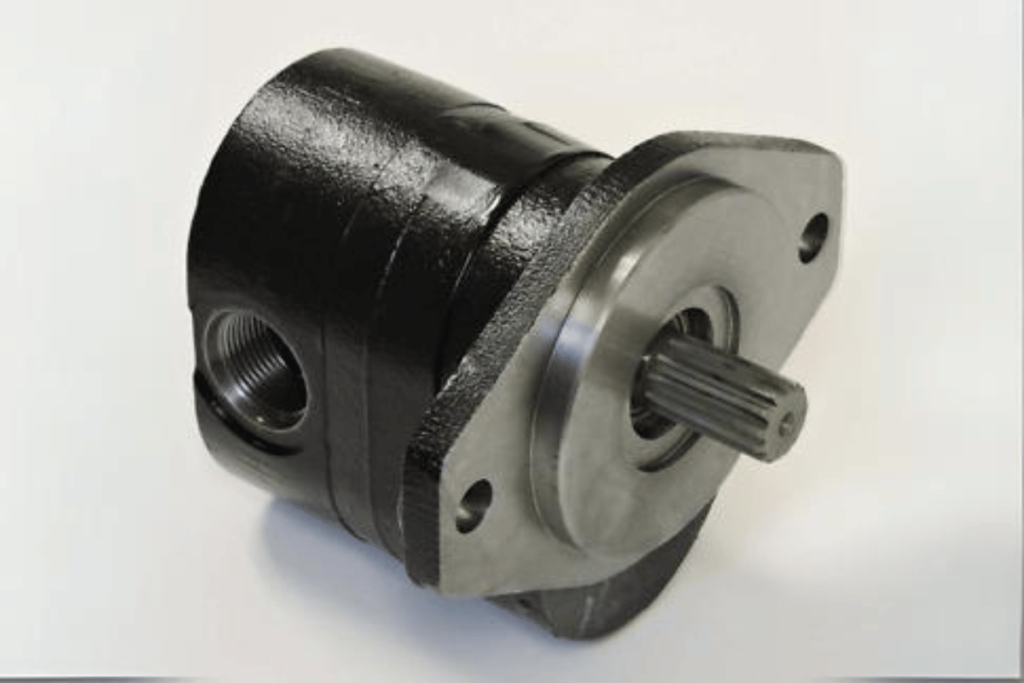
2. External Gear Pumps: In this design, the fluid is moved by two meshed gears rotating outside each other. This kind of setup is more straightforward than the internal type and is often used when dealing with lower-viscosity liquids. External gear pumps offer directness in construction reliability in terms of maintenance as well as providing high flow rates; hence, they are most commonly employed in industries involving large quantities, such as lubrication systems or fuel transfers for engines, etcetera.

  • Flow Rate: 5 GPM – 400 GPM (Dependent on Configuration)
  • Pressure Rating: Commonly Rated For Up To 3000 PSI
  • Efficiency: Can Achieve Over 90%
  • Viscosity Range Effective For Fluids With Viscosities Ranging From 1cSt –1000cSt.

Knowing these categories and their technical characteristics helps one choose the right pump for a given hydraulic system, thereby ensuring maximum efficiency coupled with reliability.

Applications of Hydraulic Gear Pumps in Industry

Hydraulic gear pumps are essential in many industries because they are efficient and can handle different viscosities. Here are some examples:

  1. Automotive Industry: Power steering and transmission systems use hydraulic gear pumps where high pressures with specific flow rates are necessary. Usually, they handle between 10 and 30GPM flow rates while tolerating up to 2500 psi pressure.
  2. Chemical Processing: They are used in the chemical industry to transfer corrosive or viscous fluids. Viscosities are limited between 30cSt and 1200cSt so that chemicals can move smoothly during production.
  3. Manufacturing Equipment: Hydraulic gear pumps inject molds or power hydraulic presses which help manufacturing machines work. These machines operate at different speeds but most fall within the range of 5-400GPM.
  4. Marine Applications: These pumps are used in hydraulic steering mechanisms and lifting equipment in marine vessels. Their ratings usually go up to 3000psi to ensure they work well under challenging conditions.
  5. Beverage Production: In the food and beverage industry, sweeteners, syrups, and oils need to be transferred, so hydraulic gear pumps come into play. Such a pump may handle fluids with viscosities ranging from one hundred thousandth poise (1cP) to one million poises(1MCP) without compromising health standards.
  6. Construction Equipment: Excavators and loaders, among other heavy machinery, require high flow rates coupled with large torques, thus necessitating the use of hydraulic gear pumps capable of delivering on those fronts.All construction works usually fall between 10 and 200GPM.
  7. Oil & Gas Industry: The transfer and processing of crude oil and lubricants greatly depends on these types of pumps. High-pressure resistant materials should be used because they can handle various fluid viscosities ranging around twelve thousand stokes(12000s).
  8. Agricultural Equipment: Hydraulic gear pumps are commonly used in tractors, harvesters and other agricultural machineries.They are similar to those used in construction works.
  9. Pharmaceutical Industry: Hydraulic gear pumps play a significant role in the pharmaceutical industry because they can handle different viscosities, which is handy when dealing with other pharmaceuticals.
  10. HVAC Systems: Hydraulic gear pumps circulate fluids, one of the many functions they perform in heating, ventilation, and air conditioning systems. They help maintain efficiency across various temperature settings.

The flow should remain constant at all times regardless of changes within the system being used, which requires it to be able to cope with various parameters.

How Do Gear Pumps Work?

how a hydraulic gear pump works

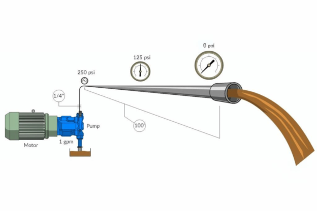
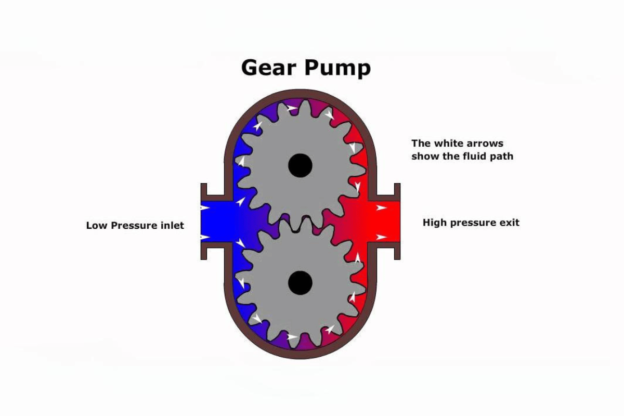
Hydraulic gear pumps work by a simple principle of positive displacement. They produce a vacuum as they rotate, which draws hydraulic fluid into the pump through its inlet. The liquid then occupies the clearance between gears and housing while they still move. Fluid is trapped and forced towards the outlet by the mechanical meshing of these components. Confined oil gets squeezed out under pressure at an exit port as one gear passes another. This process continues without interruption, supplying uniform flow rate of hydraulic liquid – making gear pumps highly efficient in different applications where reliability matters most among other factors affecting their performance such as design type used, clearance between moving parts involved and viscosity levels exhibited by pumped media among others needed parameters for successful operation with this type of machinery being considered reliable enough even at higher pressures commonly found within industrial environments where continuous delivery over extended periods becomes necessary.

Basic Working Principle of Gear Pumps

Positive displacement mechanism is the main principle of the working of gear pumps. When their teeth intermesh, they create cavities filled with liquid and then transferred from the input to the output. In this process, fluids are sucked by a rotating gear that causes a vacuum through its action. It then pushes them out as another comes into contact, maintaining continuous flow while trapping some amounts within itself.Several technical considerations should be taken into account, including:

  1. Flow Rate – It is usually expressed in gallons per minute (GPM) or liters per minute (LPM). It shows how much fluid can be moved by pump within a specific time period. Higher rates mean more work is done, thus making such devices efficient for most tasks.
  2. Pressure Rating—This refers to maximum operational pressures stated in Pounds per Square Inch (PSI) or Bar. An appropriate pressure rating must be chosen to handle the demands required by particular applications effectively.
  3. Viscosity—This measure denotes the thickness or thinness level exhibited by any given fluid being pumped, measured in centistokes (cSt). Gear pumps have a wide range adaptability, and some models can even pump up to several thousand centistokes depending on the different uses they may be subjected to.
  4. Efficiency Of The Pump – Usually expressed as a percentage signifying how much input power gets transformed into hydraulic energy outputted by said device. Greater efficiencies save energy during usage since lower percentages produce less heat while operating.
  5. Gear DesignThree common types of gears are used, namely spur, helical, and beveled. Each one has its own pros and cons, such as noise level production and efficiency rate achieved at various speeds. Different designs will suit different industrial needs based on the specifications required for use under certain conditions.

These parameters act as guidelines when selecting the appropriate gear pump for any given task, ensuring the best performance possible during all stages involved in various industrial processes.

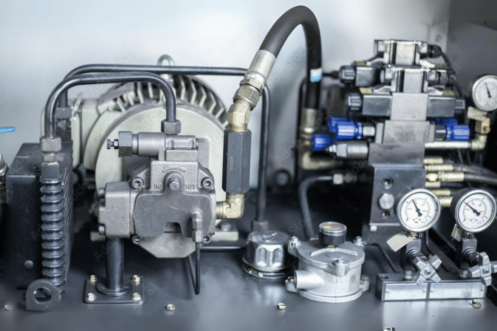
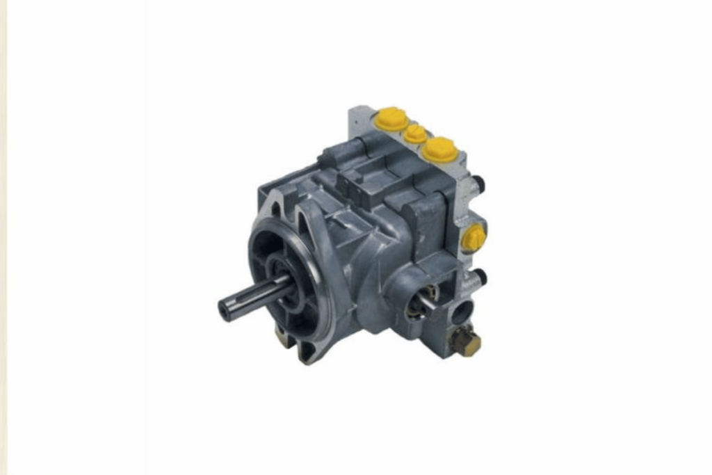
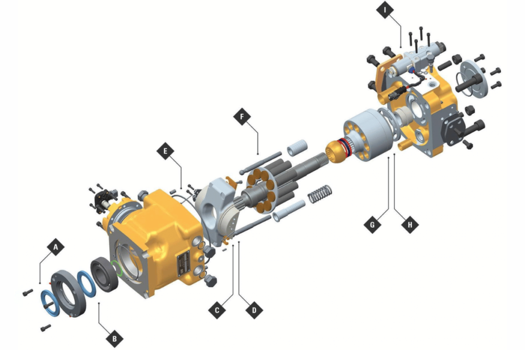
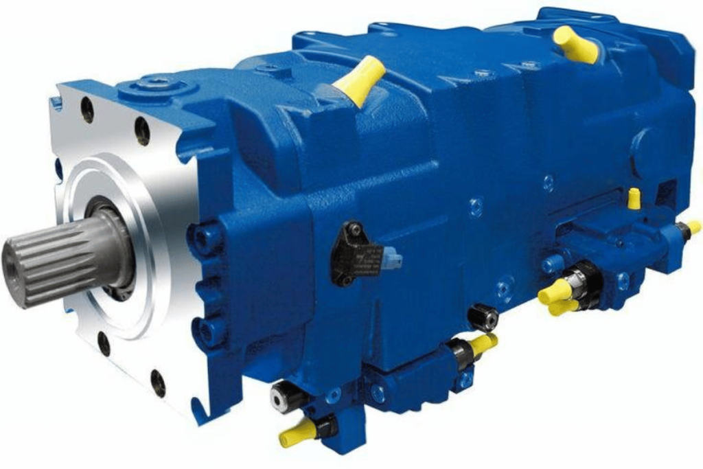
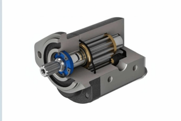
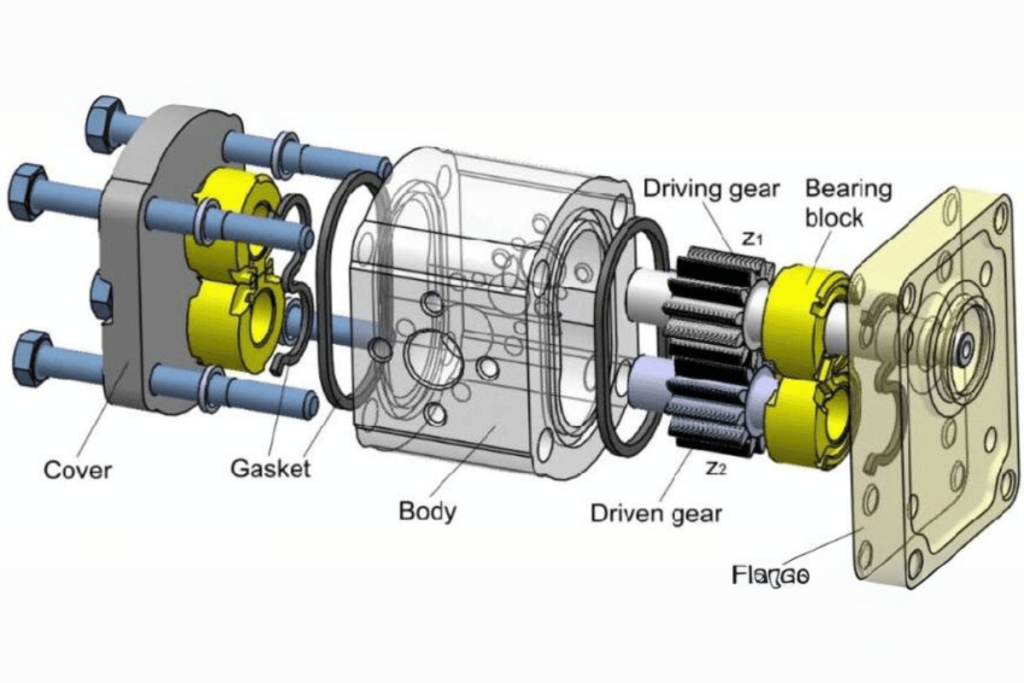
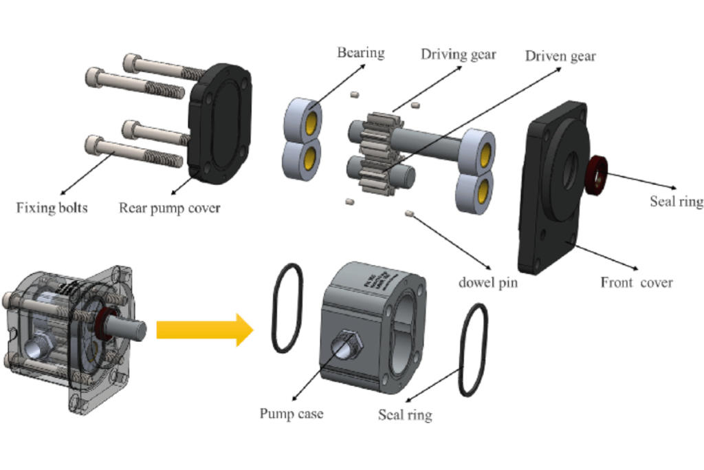
Critical Components of a Hydraulic Gear Pump

Hydraulic gear pumps are essential in many industrial applications, they can only be appreciated when we know what makes them perform effectively. Presented below are the main parts:

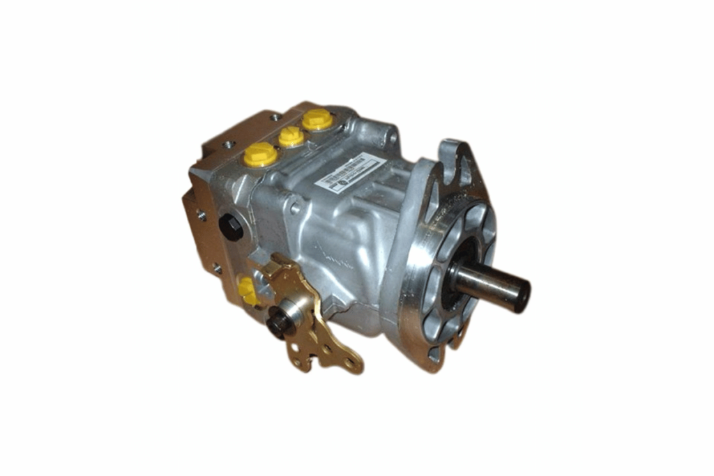
  1. Casing: The outermost part encloses all other components of a pump. It protects them from external forces and ensures the required internal pressure is maintained.
  2. Gears: These elements transfer hydraulic fluid. They are usually either straight-cut or helical, with each having its own advantages, such as lower noise levels during operation or higher efficiency rates.
  3. Suction and Discharge Ports: Openings through which liquid enters into and leaves out of the pump. Their design affects flow characteristics as well as efficiency.
  4. Bearings hold rotating gears in place within the unit’s housing. The right choice must be made for the longevity and stable operation of any bearing used here.
  5. Seals and Packing: These prevent hydraulic fluid from leaking out of a pump. Seals should remain intact to keep up pressure and contain fluids properly.
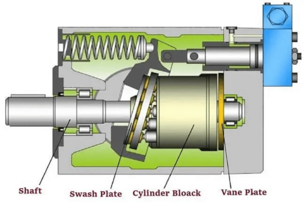
  6. Drive Shaft: This connects motor with a pump enabling rotation of gears. Its design should consider required torque while minimizing wear on itself or other parts involved.
  7. Pressure Relief Valve: It safeguards against over-pressurization by ensuring safe working conditions within the system, hence protecting against possible damages that may occur otherwise.
  8. End Plates: Gears are sandwiched between these plates, which also hold them in position, additionally providing support to overall structure integrity where necessary, such as preventing leakages through seals fitted on top surfaces thereof
  9. Flow Control Valve – regulates the amount speed at which oil flows throughout entire arrangement, thus enhancing effectiveness coupled with appropriate supply this kind energy where required, most being attained simultaneously =
  10. Cooling System – necessary for maintaining pump temperature levels within acceptable range, especially during extended use periods thereby optimizing performance life expectancy by large margin considerably too far longer than expected without such provisions or measures taken into consideration whatsoever

Thus, knowledge about these technical parameters, including but not limited to pressure ratings, efficiencies, and gear designs, among others, is important in selecting the right hydraulic gear pump for a particular task and maintaining it.

Fluid Flow and Gear Rotation Mechanism

The hydraulic gear pumps’ fluid flow and gear rotation mechanism is very essential to their operation. To put it simply, the rotation of gears produces a vacuum that sucks in liquid; this liquid then gets trapped between the teeth of the gears which carry it up to an outlet. Below are some critical technical terms associated with this process:

  1. Flow Rate: It is measured in liters per minute (L/min) or gallons per minute (GPM) and shows how much fluid is being displaced by the pump within specific time frames. Higher rates should be used where high demands are expected to increase efficiency.
  2. Viscosity: This characteristic measures how easily a fluid can move through something by resisting its flow; thus, it directly influences to what extent that particular fluid moves smoothly inside our pumps. Knowing range of viscosities suitable for your machine will significantly help you achieve better results
  3. Gear Ratio: The ratio between the number of teeth on the driven gear and the driving one determines the speed and torque required from them simultaneously. These two quantities must always balance each other out perfectly if we want everything else about the hydraulic system to function correctly. The proper selection made at this point enhances the overall efficiency levels attained by any given setup.
  4. Pressure Rating: This rating indicates the maximum pressure limit that different types of pumps can handle. It is usually expressed in pounds per square inch (PSI) or bar units, which is critical when choosing the appropriate pump for relevant applications.
  5. Efficiency Rating: Efficiency ratings show how well energy has been utilized during operation – they’re expressed as percentages where higher values mean good utilization and lower ones imply poor use. In other words, it compares input power with output power got from a given device under consideration i.e., Higher ratings indicate that more was supplied into system hence less operational costs incurred

These parameters ensure that the pump works effectively for its specific application without compromising reliability or lifespan. Failure to consider them could lead to a wrong choice being made among available options, hence ending all this knowledge about hydraulic gear pumps and what they can do for us.

Advantages and Disadvantages of Using a Gear Pump

how a hydraulic gear pump works

Pros

  1. Efficiency: Gear pumps are good at pumping steady fluid flows, which makes them useful in various fields.
  2. Size: They are relatively small, which means they can fit easily into hydraulic systems without much modification.
  3. Adaptability: They work well with liquids of various viscosities i.e. from thin to thick consistency fluids.
  4. Long life: Due to their robust structure, these pumps can withstand heavy conditions and serve for a long time.
  5. No Pulsation: Gear pumps are handy in applications needing uniform pressure, as they deliver fluid steadily without pulsing.

Cons

  1. Priming Limitations: Setting up gear pumps may not be easy since most of them have to be primed before use, which complicates the installation and maintenance processes.
  2. Pressure Restriction: Some designs may not allow for very high pressure, hence limiting the areas where this type can be applied despite its capability in terms of pounds per square inch ratings (PSI).
  3. Viscosity Sensitivity: When viscosity levels significantly change, such machines affect performance and effectiveness.
  4. Wear Tear : Over time continuous interlocking gears will wear out thereby requiring regular replacements and servicing of parts used on such devices.
  5. Noise Production: Gear pumps might produce more noise pollution than other kinds, depending on the environment in which they are operated.

Benefits of Hydraulic Gear Pumps in Various Applications

Hydraulic gear pumps have gained popularity in many industries because they possess certain merits. These include:

  1. Uniform Output: They deliver a constant flow rate consistently which is necessary for accurate hydraulic control in applications like construction equipment and manufacturing machinery.
  2. Trim Size: These devices’ compact design makes them appropriate for use where space is limited, such as the automotive and aerospace industries, enabling more flexible system designs.
  3. Wide Range of Viscosity: Gear pumps can accommodate various fluid viscosities in industries like oil and gas, food processing, and pharmaceuticals, where different substances need to be pumped.
  4. Efficiency: Gear pumps are cost-effective, as they have low energy loss due to their high volumetric efficiency, making them suitable for energy-consuming operations.
  5. Reliability: This equipment is built strong enough to work under harsh conditions, so it can operate effectively in harsh environments like mining areas or agricultural fields, where machines are frequently subjected to rough treatments.
  6. Less Servicing Required: Unlike some complex types of pumps that may demand extensive maintenance on account of their intricate nature – this one does not require much attention because its design is simple though it wears out with time hence routine checks should be done.
  7. Sealing Capability: Hydraulic systems need to prevent leaks; therefore, any pump intended for use in such systems must possess good sealing properties to meet safety standards and environmental compliance—gear pumps excel here, too!
  8. Scalability: These gadgets allow both small and large-scale production setups, making them applicable across different sectors ranging from light-duty machinery to heavy industrial devices.
  9. Widespread Usefulness: Many people know about hydraulic gear pumps hence finding spare parts or servicing them is never difficult locally or internationally since numerous suppliers are dealing with these items worldwide which ensure quick availability wherever required.
  10. Cost-effectiveness – In most cases, initial costs associated with purchasing hydraulic gear pump tenders usually turn out cheaper over the long run due to their efficiency and reliability when compared to other pump types.

Gear pumps typically operate at pressures of up to 3000 psi or higher depending on the design as technical parameters. They come in different sizes for various flow rate requirements, usually ranging from a few liters per minute to over 1000 liters per minute. Hydraulic gear pumps can achieve efficiency levels of around 90% under optimum conditions, thus making them cost-effective across a wide range of applications.

Limitations and Challenges of Gear Pumps

While they have many benefits, hydraulic gear pumps also come with some limitations and challenges that users need to know about.

  1. Limited Viscosity Range: Gear pumps typically work well with low-viscosity liquids. However, they wear out more quickly or become less efficient when used with high-viscosity fluids, so it is necessary to select applications in such cases carefully.
  2. Pulsation and Noise: Gear pumps generate flow pulsations as they operate which can cause noise and vibration in a system. This may affect the performance of machines generally or increase their wearing rate over time.
  3. Temperature Sensitivity: Hydraulic fluids lose their lubrication properties under high temperatures, affecting pumping efficiency and causing thermal degradation. Operators should, therefore, monitor operating temperature levels to avoid overheating.
  4. Sensitivity to Contaminants: Gear pumps are easily damaged by dirt particles within them or dirty fluids passing through them. Therefore, the best thing to do is ensure a clean working environment throughout to achieve reliability and long-life service from these devices.
  5. Pressure Limitations: Gear pumps can handle a maximum working pressure of 3000 psi upwards, but exceeding this limit will cause the system to fail suddenly. Therefore, it is important to stick within specified operational boundaries while not overloading any part of the machinery beyond what it was designed for.
  6. Uneven Wear Patterns: Gear pumps sometimes wear unevenly, mainly if used with abrasive media. Therefore, frequent check-ups should be carried out, and worn-out components should be promptly replaced whenever necessary.

In conclusion, although they serve well in most areas as far as efficiency is concerned there still exist certain limits which one needs always take cognizance of and put proper corrective actions into place accordingly.

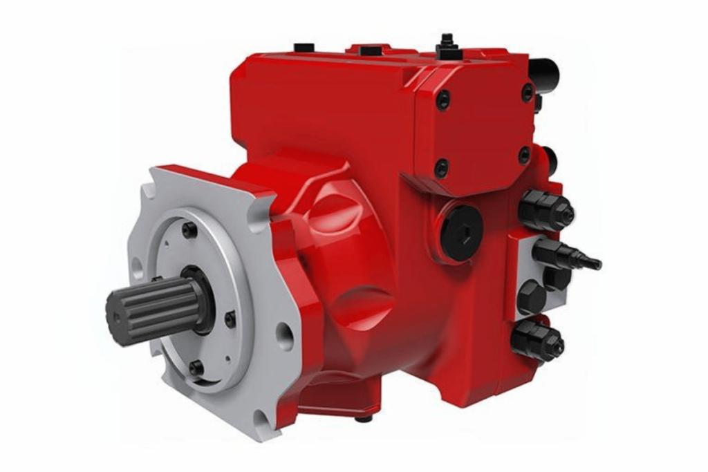
Comparison with Other Types of Hydraulic Pumps

how a hydraulic gear pump works

When we contrast gear pumps to other hydraulic pump types like vane pumps or piston pumps, it becomes clear that they differ in performance, efficiency and suitability for various uses.

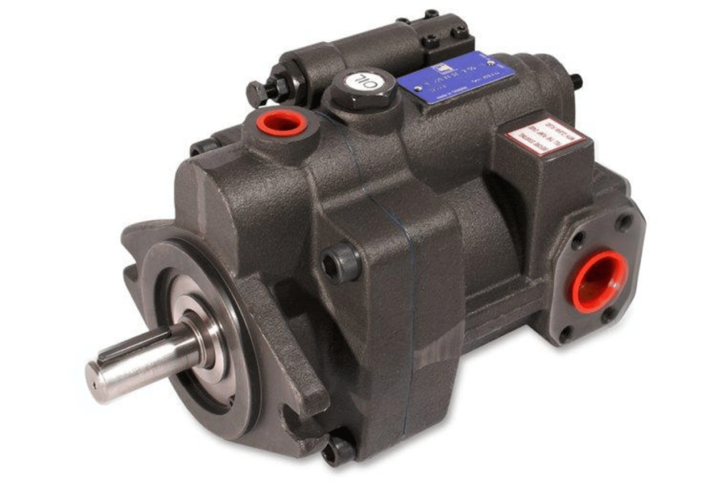
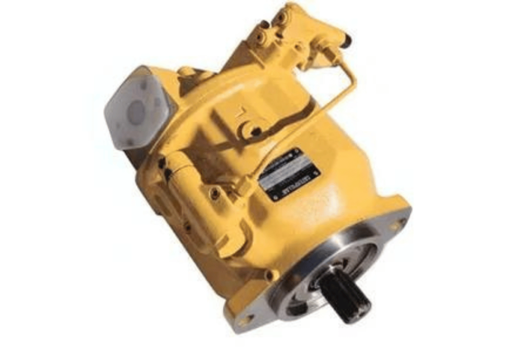
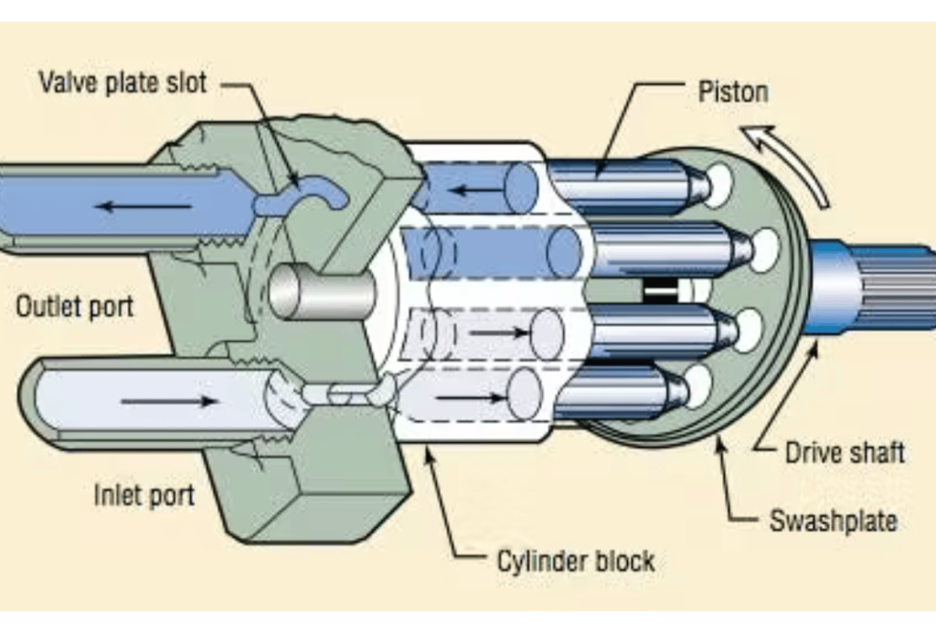
  1. Piston Pumps: These types of pumps are best known for their ability to create higher pressures. They’re, therefore, commonly used where great force is needed. However, they are expensive and complicated compared with gear pumps which require less maintenance work that is more intricate. Also when the fluid flow changes constantly, their efficiency is better.
  2. Vane Pumps: operate more smoothly and quietly than gear pumps while still being able to handle different applications effectively. Nevertheless, just like the gear pumps, they become less efficient as viscosity changes. Additionally, self-priming capabilities are usually better for them than with gear pumps.
  3. Performance and Efficiency: Gear pumps are designed compactly to work well in environments with high viscosity levels while being durable; on the other hand piston or vane pumps could be more versatile under dynamic fluid conditions. Each pump has its own area of application where it can perform optimally, but constant flow requires a gear pump, whereas a piston pump should be used in systems with high pressures.
  4. Cost and Maintenance: For many industrial applications gears have lower initial costs and more straightforward maintenance requirements than pistons or vanes which also extend their life cycle thus reducing downtime significantly.

Knowing these differences will enable one to select the right hydraulic pump for his project, depending on specific needs and available resources.

Gear Pumps vs. Vane Pumps

Comparisons between gear pumps and vane pumps require the evaluation of various parameters that determine their applicability in different situations. Below is a brief summary from reputable industry websites:

1. Working Pressure:

  • Gear Pumps: They can generally handle pressures of up to 5000 PSI, hence suitable for high-pressure applications.
  • Vane Pumps: Typically function well within lower pressure limits around 1000-3000 PSI, which may restrict usage where demand is high.

2. Rate of Flow:

  • Gear Pumps are known for providing uniform flow rates. Depending on size and speed, they give an extensive range of outputs, with a maximum flow rate generally exceeding 1000 GPM.
  • Vane Pumps: Provide variable flows based on design, often ranging between 10 GPM and 500 GPM, which can change due to fluid viscosity.

3. Viscosity Capability:

  • Gear Pumps: Designed for use with highly viscous fluids as they can pump thick liquids without experiencing much cavitation
  • Vane Pumps are inefficient for handling fluids with high viscosity because their performance deteriorates as viscosity increases, resulting in reduced flow.

4. Maintenance:

  • Gear Pumps: Standard maintenance procedures should be followed but this type has fewer movable parts, meaning less time spent on repairs leading to lower operational costs
  • Vane Pumps: More intricate since they have rotating vanes necessitating frequent servicing and replacement of components

5. Costs:

  • Gear Pumps: Relatively cheaper during initial purchase thus making them more cost-effective for many applications.
  • Vane Pumps Have higher prices due to their complexity in design, but sometimes, this may be justified in cases where noise reduction or smooth running conditions are needed.

6. Noise Levels:

  • Gear Pumps: Usually produce more noise when operating than vane pumps do.
  • Vane Pumps: Operate quietly thereby favoring environments sensitive to sound disturbance.

These technical aspects are important in choosing between gear pumps and vane pumps based on application requirements, financial limitations, and performance expectations.

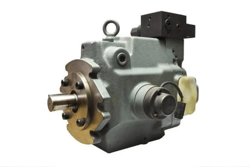
Gear Pumps vs. Piston Pumps

Comparing gear pumps and piston pumps involves looking at various technical parameters that affect their suitability for different applications. Below is a brief description of these parameters as per insights from top industry sources:

1. Flow Rate:

  • Gear Pumps: They usually give constant flow rates that may vary between few gallons per minute (GPM) and over 1000 GPM. This even flow is suitable for applications that need steady pressure.
  • Piston Pumps: The number of strokes and displacement volume of the pistons can be used to adjust the variable flow rates provided by this type of pump. It is therefore ideal for use when high pressure is required at specific intervals.

2. Viscosity Handling:

  • Gear Pumps: Positive displacement devices are good at pumping high-viscosity fluids because they eliminate cavitation, which would otherwise disrupt continuous flow.
  • Piston Pumpscan handle different viscosities, but their performance tends to deteriorate with very thick liquids, thereby reducing efficiency levels.

3. Efficiency:

  • Gear Pumps: Gear pumps generally have high efficiencies, consuming less power, especially when dealing with low-viscosity fluids.
  • Piston Pumps: Specific applications can achieve high efficiency, mainly by generating substantial pressures; however, a continuous duty cycle may not be as efficient as a gear pump.

4. Maintenance:

  • Gear Pumps: These types of pumps require less maintenance because they have fewer moving parts, lowering operational costs and minimizing downtime.
  • Piston Pumps: Because their design is complex, maintenance frequency might increase along with repair needs. Seals and pistons wear out easily during operation, leading to frequent breakdowns or replacements, thereby increasing downtime durations.

5. Cost:

  • Gear Pumps: They have lower initial costs than piston pumps making them more affordable across different uses.
  • Piston Pumps: Due to their intricate nature, piston pump systems require higher upfront investments compared to gear pump systems, though such expenses may only be justified under certain performance conditions based on specific application requirements.

6. Noise Levels:

  • Gear Pumps tend to be noisy during operation, which can be a challenge in environments that are sensitive to noise pollution.
  • Piston Pumps: Quieter operations make it better suited for places where one needs to minimize unwanted sounds.

When choosing between gear and piston pumps, these technical parameters should be considered relative to the particular application so that the selected pump can effectively satisfy operational needs while considering cost.

Choosing the Right Pump for Your Needs

When you are choosing a pump for your particular application, some technical parameters have to be considered according to your operational needs. After looking at the best online resources available out there, these are the main points to weigh up:

1. Application Type:

  • To determine which pumps are suitable, determine if it is for low-viscosity fluids, high pressure, or continuous use.

2. Efficiency Requirements:

  • Gear Pumps can save energy when used in low-viscosity fluid applications although piston pumps work well under such conditions especially where high pressures must be realized.

3. Maintenance Considerations:

  • Evaluate maintenance requirements based on your environment. Gear pumps would suit this need if you need reduced downtime and operating costs. They have few moving parts, so less maintenance is required. Conversely, if frequent servicing can be done within the system being used, select piston pumps because of their potential in high-performance areas.

4. Cost Analysis:

  • Look at both upfront and life cycle expenses involved. While initial investment may favor gear pumps over piston ones, which might look expensive initially but perform better in high-performance areas, thus saving money over time.

5. Noise Level Impact:

  • Consider surrounding conditions. If noise happens to be a major factor of concern, then use piston pump systems. They are silent, making them ideal for delicate environments. However, gear types should not be ruled out just yet, as they still possess other advantages.

By systematically considering these factors one by one, you can make technically sound decisions and save on costs through proper maintenance measures.

Future Trends in Hydraulic Gear Pumps

how a hydraulic gear pump works

Many new trends are expected to influence the future of hydraulic gear pumps. These shifts coincide with evolving technology and industry needs. One such trend is a focus on energy efficiency, which has prompted manufacturers to create higher-performance pumps that use less power. This demand aligns with broader efforts across sectors to lower carbon footprints and save money on operations. Furthermore, real-time data analysis enabled by Internet of Things (IoT) integration is transforming pump monitoring and maintenance through predictive upkeep and reduced downtimes.

Additionally, the drive for smaller sizes and lighter weights in mobile applications or tight spaces where efficiency and space-saving designs matter most is gaining momentum. Finally, sustainability is becoming essential with more companies looking into environmentally friendly materials or processes used in making hydraulic pumps. Such trends indicate a changing landscape for this sector as it responds to global calls for greater efficiency coupled with technological advancements.

Innovative Designs in Gear Pump Technology

Gear pump technology is improving quickly to match the demands of current industries. These improvements include making high-torque gear pumps, which have higher flow rates without losing efficiency. This type of pump usually has well-made gears that reduce internal friction, thus saving energy and reducing noise.

Another change is creating a variable displacement mechanism that allows pumps to vary their output according to demand, saving energy and making systems more responsive. Furthermore, science has developed new materials, such as composites and lightweight ones, which are used in building them. This helps in reducing their overall weight while increasing durability as well.

Parameters

  • Torque Rating: Higher torques ratings enable pumping highly viscous fluids at more significant flows with increased efficiency.
  • Displacement: Variable displacements may better match a pump’s output and the system’s needs, optimizing performance.
  • Efficiency Rating: Better designs often mean less power consumption, reflected through higher efficiency ratings.
  • Noise Level: More refined engineering methods lead to quieter operations, especially necessary for a calm environment.
  • Material Properties: Advanced materials can increase wear resistance, protecting against corrosion and increasing the lifespan of these machines.

These changes indicate our efforts towards operational effectiveness, environmental sustainability, and reliability improvement in hydraulic systems.

Environmental Impact and Energy Efficiency

In their design and operation, one of the most important things to consider about hydraulic pumps is how they affect the environment. These developments for energy efficiency are cost-effective and help reduce the carbon footprint that comes with using a pump. Here are some of those strategies:

  1. Variable Displacement Mechanisms: By allowing the output of a pump to change depending on what’s needed, these mechanisms save power while reducing wastage through it which means lower emissions and more sustainable development.
  2. High Torque And Efficiency Ratings: Higher torque ratings enable better handling of highly viscous fluids, thus cutting down on energy consumption required for this purpose. Eventually, this will result in low power usage. Pumps with good efficiency rates will demand less energy, leading to reduced greenhouse gas emissions.
  3. Noise Levels Reduction: Enhanced engineering can make pumps quieter during operation and less destructive to wildlife or people around them, thereby fostering a better relationship between man and nature.
  4. Advanced Materials: When materials that do not wear off easily due to corrosion are used in making these machines, it not only extends their lifetime but also decreases the frequency with which they need replacing; hence, over time, fewer resources will be consumed as well as generate less waste.

Manufacturers who design hydraulic pumps based on these technical specifications show an interest in sustainability, which further improves the overall environmental performance of their products.

Predictions for the Hydraulic Pump Market

According to technological advancements and increasing demand from different sectors, the hydraulic pump industry is anticipated to achieve substantial growth in the future. The predictions are as follows:

  1. More use of intelligent systems: It is predicted that there will be more adoption of Internet of Things (IoT) devices in hydraulic pumps. These devices allow for real-time monitoring and prediction of maintenance requirements, thus making operations efficient while minimizing downtime. The technical parameters involved here comprise sensors used in monitoring pressure and flow rate, which provide information necessary for optimally managing performance.
  2. Shifting to mobile and compact solutions: As industries look towards improving their flexibility and portability, they should expect an increase in mobile hydraulics. These are designed with lightweight features besides being smaller in size but still having high torque outputs that can handle heavy-duty applications effectively.
  3. Sustainable Innovations: Environmental consciousness has led people to think about sustainable development, even when designing such products. Therefore, we may witness pumps with better energy ratings, those that meet emission standards set by regulatory bodies among other things, characterized by extended life span courtesy of advanced materials utilization being introduced into this market soon enough
  4. Renewable energy application emergence: Hydraulic power systems have found themselves helpful within renewable energy areas, especially during wind or even hydroelectricity generation stages, where variable displacement type high-performance units must be employed to save energy and ensure efficiency.
  5. Market consolidation & collaborations: Manufacturers could join hands through partnerships to create innovative solutions, thereby reshaping industry competitiveness through mergers expected between some companies and other moves within this segment. Collaborative ventures focusing on research coupled with development activities might result in breakthroughs concerning efficiency metrics together with advanced material application, thus improving overall quality standards alongside environmental friendliness relating to hydraulic machines.

Overall, sustainability needs, while addressing these trends, can help shape production models within the hydraulic sector, hence meeting new demands from various sectors supported by appropriate technical specifications.

Frequently Asked Questions (FAQs)

how a hydraulic gear pump works

1. What are the main applications of hydraulic pumps?

Hydraulic pumps are widely used in various industries, including construction, agriculture, manufacturing, and renewable energy. They are essential for powering machinery, hydraulic systems, and equipment that require fluid power for operation.

2. How do I choose the right hydraulic pump for my application?

Selecting the appropriate hydraulic pump involves considering several factors, such as the required flow rate, pressure rating, and the viscosity of the hydraulic fluid. Additionally, evaluating the specific operational requirements of your machinery and considering factors like size and energy efficiency are crucial.

3. What advancements are being made in hydraulic pump technology?

Recent advancements in hydraulic pump technology include the integration of intelligent sensor systems for real-time monitoring, the development of compact and lightweight designs, and innovations geared toward enhancing energy efficiency and sustainability.

4. How do hydraulic pumps contribute to sustainability?

Hydraulic pumps aid sustainability through improved energy efficiency, reduced emissions, and the use of eco-friendly materials. Their role in renewable energy applications also supports the transition to greener energy sources.

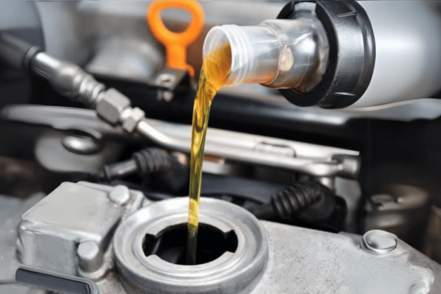
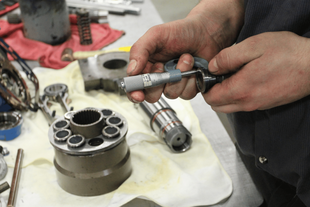
5. What maintenance is required for hydraulic pumps?

Regular maintenance of hydraulic pumps includes checking fluid levels, inspecting for leaks, cleaning filters, and ensuring all components function correctly. This helps extend the pump’s lifespan and ensures efficient operation.

do hydraulic pumps create pressure

How Does a Hydraulic Pump Create Pressure and Flow?

Hydraulic systems depend on hydraulic pumps because hydraulic pumps convert mechanical energy into liquid power. Knowing how to generate pressure and flow with these mechanisms is critical for jobs in engineering, construction or manufacturing among others. This article will examine what makes hydraulic pumps tick, including different kinds and their operational principles. We want readers to come away from this piece and understand everything about what makes hydraulics work – breaking it down into easy-to-understand bits. We also cover when they’re used, why good fluid movement matters in industry and more! Don’t worry if you’re new or need a refresher; there’s something here for everyone from beginners to experts looking for new ideas!

How Does a Hydraulic Pump Work?

do hydraulic pumps create pressure

Typically, hydraulic pumps convert mechanical energy from an engine or motor into hydraulic energy. Then this hydraulic energy becomes useful for generating fluid flow and pressure within a hydraulic system. In most cases, it is achieved by allowing the movement of oil, which is a type of hydraulic fluid, through a closed-loop mechanism. The pump creates a partial vacuum that sucks oil from the storage reservoir as it works; hence this fluid should be pressurized in different ways, like the rotation of gears in gear pumps or piston displacement area in piston pumps.

The work done by these machines consists of moving fluids via hoses and pipes up to cylinders, which act on other parts, thereby making it possible for heavy machinery to lift, push, or pull, among others. Designing efficiency and effectiveness levels of operation depend upon factors like flow rate design system pressure, among others, that should be considered when looking at a given instance where they may fail to meet expected standards performance-wise. However, without them, many things cannot work out well, especially in industries such as manufacturing and construction, because they create reliable solid movement power required for various tasks during the production process.

What Is a Hydraulic Pump?

Hydraulic power is a mechanical apparatus that converts mechanical energy into hydraulic energy by the force of fluid motion. Hydraulic pumps create the flow of hydraulic fluids needed for different hydraulic systems. Gear pumps, piston pumps, and vane pumps are some standard hydraulic pumps that work on different principles to displace fluids.

There are some critical technical parameters for hydraulic pumps; these include:

  • Flow rate: It is the volume of fluid that can be moved by the pump in a given time usually expressed in gallons per minute (GPM) or liters per minute (L/min). The flow rate is significant because it determines how fast a system can operate.
  • Pressure rating: This shows the highest pressure a pump can withstand usually indicated in pounds per square inch (PSI) or bar. This is necessary for safety reasons as going beyond this value may cause the pump to fail or leak.
  • Efficiency: It refers to the ratio between output power in hydraulics and mechanical input power, which is given as a percentage. High efficiency means less energy wastage during conversion from one form of energy to another.
  • Viscosity: This refers to thickness if you like of any given liquid; it affects its ability to move through any particular part such as our pump here today. Viscosity should be maintained correctly since too thin or thick fluids will lower effectiveness.

These parameters must be considered when choosing hydraulic pumps so that they suit applications and meet operational requirements depending on where they’ll be used within different kinds of systems relying upon them.

How Does a Hydraulic Pump Create Flow?

A hydraulic pump is a device that moves fluid within a system by converting mechanical energy into hydraulic energy. This is achieved by taking fluid in during an intake stroke and then expelling it on the opposite discharge stroke, as will be dictated by the design of the particular pump. For example, gear pumps create a vacuum through their rotating gears to draw fluids into them before trapping them in between those same turning gears which then forces these trapped liquids outwards again. In contrast, piston pumps produce pressure differentials through reciprocating pistons thereby enabling controlled suctioning and discharge of fluids.

Technical parameters concerning flow creation in hydraulic pumps:

  • Rate of Flow: The speed at which action happens is dictated by how much liquid this machine can move. When more quantities are displaced per unit time – higher rates are realized thus influencing performance since systems work faster with increased flow.
  • Pressure Rating: The ability to handle high pressures is necessary to pump fluids effectively. It should do so because if not enough force were applied behind any given volume, then there would be no way that such could ever reach its destination or pass through various points without leaking out along the path taken by these materials while being conveyed within pipes and other channels used for this purpose.
  • Productivity—Many machines conserve power when they lose little energy during use, thereby allowing maximum mechanical energy conversion into flow; otherwise, this is important mainly due to concerns over minimum wastage and operational cost savings.
  • Viscosity: The thickness needs to match with the type and application where it’s being used because if too thin won’t create enough pressure; on flip side if too thickly won’t go through easily leading wearing out more quickly as well reduction in performance levels.

Pumping efficiency also depends on other factors, but understanding these will help you choose the correct hydraulic pump for your system, ensuring the best possible flow generation efficiency.

What Role Does a Pump Play in a Hydraulic System?

A pump is a crucial part of any hydraulic system. Its primary purpose is to convert mechanical energy into hydraulic energy by moving fluid within the system. This sets up a flow of hydraulic fluid so that power can be transmitted through the rest of the system. There are several technical aspects by which one may describe what pumps do:

  • Flow Rate: Pumps need to produce enough flow rate such that hydraulic actuators (for example cylinders and motors) get supplied with adequate amounts of fluid for them operate properly; this ensures smooth and responsive movements.
  • Pressure Rating: A pump must create and maintain the necessary pressure levels to drive liquids against resistance in any given arrangement or setup; this becomes paramount because it helps overcome loads while still performing under different operational conditions.
  • Efficiency: A pump’s efficiency is directly proportional to operation costs in the entire hydraulic system. When an energy-saving device is used, less energy is consumed, thus saving more. However, if higher outputs per minute are possible, this should ensure good power transfer while reducing energy wastage.
  • Viscosity: Different types of pumps can be selected depending on the viscosity levels exhibited by various fluids used within systems. A suitable one should not cause excessive wear or tear due to overstraining caused by wide-ranging changes in liquid thicknesses during operation periods, among other things.

In summary, the pump affects the performance of a hydraulic system through flow rate, pressure, efficiency, and fluid characteristics. Correctly selecting and maintaining them ensures reliability, efficiency as well long life for use in hydraulics applications.

What Are the Common Types of Hydraulic Pumps?

do hydraulic pumps create pressure

Positive and non-positive displacement are the two main categories of hydraulic pumps.

  1. Positive Displacement Pumps: Gear pumps, vane pumps, and piston pumps fall into this category—these work by capturing a fixed amount of liquid and forcing it into the discharge. Gear pumps’ design simplicity and reliability make them famous, while vane pumps offer smoother flow with better efficiency at lower pressures. Piston pumps have high pressure and flow capabilities, making them suitable for heavy-duty applications.
  2. Non-Positive Displacement Pumps: On the other hand, these rely on rotational energy instead of creating a set displacement of liquid like centrifugal ones do. They are mainly used when pumping steadily at low pressure is needed, such as in agriculture or chemical processing.

The selection process for a hydraulic pump should consider specific application requirements, including pressure levels, flow rates, fluid types, etcetera. Each type has its own purpose, contributing to the overall effectiveness and performance of hydraulic systems across different industries.

What Is a Gear Pump?

Gear pumps are positive displacement pumps that use gears to pump fluid through mechanical motion. They work by having two or more gears rotating in a casing, which creates suction that draws liquid into the pump and forces it out through the discharge port. Gear pumps are known for being straightforward, reliable, and able to handle high-viscosity fluids.

Technical Parameters:

  1. Flow Rate: The flow rate of gear pumps can vary widely – from a few litres per minute to several thousand litres per minute depending on gear size and rotational speed.
  2. Pressure: These pumps can operate at high pressures, commonly exceeding 200 bar (approx. 3000 psi) in industrial applications; some specialized models can deal with pressures as high as 600 bars (around 8700 psi).
  3. Viscosity Range: Gear pumps can handle different fluid viscosities ranging typically between 1 cP (centipoise) for low-viscosity liquids and 1,000,000 cP for high-viscosity materials; however some types are designed specifically for thick substances such as slurries or adhesives.
  4. Temperature Limitations: The typical working temperature range for gear pumps is -40°C to +150°C (-40°F to +302°F), but this may be increased with use of unique materials.
  5. Efficiency: Gear pumps usually have pretty good volumetric efficiency, often reaching around 90%—95%; thus, they are suitable for accurate fluid metering/transfer duties.

Gear pumps have been adapted into many design forms to suit various applications, such as the automotive industry, hydraulic systems, chemical processing industry, etc., where reliability of operation remains crucial.

How Does Vane Pump Work?

Vane pumps work by the rotation of blades in a circle-shaped rotor. These blades move to and fro in slots as the rotor spins, creating chambers with different capacities. The movement leaves a void into which fluid is sucked during the intake stroke before being pushed out during the discharge stroke thus keeping liquid flowing continuously.

Technical Parameters:

  1. Flow Rate: Depending on their size and design specifications, vane pumps can deliver anywhere between a few gallons to several hundred gallons per minute.
  2. Pressure: These devices usually operate at pressures up to 175 psi (approximately 12 bar), though some models can handle higher pressure for specialized applications.
  3. Viscosity Range: Vane pumps often manage viscosities ranging from low to moderate up to about 1500 cP so that they can handle fluids used in various industrial processes.
  4. Temperature Limitations: While most are designed for temperatures within the -20°F to 200°F (-29°C to 93°C) range, others may be made of materials that enable them to withstand higher temperatures.
  5. Efficiency: Most vane pumps usually achieve good efficiency levels between 80% and 90% on average, which guarantees reliable metering and transfer operations performance.

Because they always pump liquids reliably over time after time without complicated maintenance requirements or failures occurring frequently unlike other types; because they have straightforward and robust construction that allows them work even under demanding conditions where space is limited but reliability must not be compromised – this is why many people prefer using such machines like automotive industry among others where uniform delivery rates need met always.

What Is a Piston Pump?

A piston pump is a positive displacement pump that uses a piston to move fluid within a cylinder. In other words, it is used for transporting liquids mechanically. While one end of the piston pushes the fluid out of the cylinder during its discharge stroke, it also draws new fluid in during the intake stroke at the same time. The design allows this type of pump to be used for any liquid in different applications, including hydraulics, chemical processing, and water supply.

Technical Parameters:

  1. Flow Rate: They have various sizes and operational designs which means they can deliver different flow rates starting from less than one gallon per minute up to over five hundred gallons per minute generally.
  2. Pressure: One of its most popular features is its ability to work with high-pressure systems. Hence, it often operates between 4000 psi (about 275 bar) or even more, making it suitable for use in hydraulic power units as well as high-pressure cleaning applications.
  3. Viscosity Range: These machines are versatile because some can accommodate both low viscous liquids and highly viscous fluids depending on how they were made.
  4. Temperature Limitations: The temperature ranges within which these devices operate may vary widely, but they usually range from -40°F to 250°F (-40°C to 121°C), depending on the materials used and the seals applied during their construction.
  5. Efficiency: Due to minimum slip & better flow controls that comes with this kind of design; hence more than 90% efficiency levels may be achieved by such pumps when all conditions are met.

They find their use in the oil and gas industry because they can withstand rough handling methods and cope with extreme environmental conditions, thus becoming known worldwide as very rugged equipment that should not be missed in any chemical plant alongside various high-pressure worksites where sometimes nothing else could work except for these things.

How Do Hydraulic Pumps Create Pressure?

do hydraulic pumps create pressure

Fluid displacement is the method by which pressure is produced in hydraulic pumps. This takes place when a pump draws fluid from a storage tank and encloses it inside one of its chambers. A mechanism such as gears, vanes, or pistons reduces the chamber’s volume, compressing the liquid and creating pressure that enters the hydraulic system.

In positive displacement pumps, pressure build-up occurs while fluid passes through the pump mechanically. For example, gear pumps do this through rotating gears, which interlock with each other, thus forming sealed spaces and forcing fluids outwards. Similarly,vane pumps use sliding vanes to make different-sized chambers, causing pressure variations.Piston pumps, on their part, employ back-and-forth moving pistons that apply force to liquids, generating high pressures required for heavy-duty applications.

Nevertheless, apart from these mechanisms, another factor also determines how much pressure gets created: impedance offered by downstream systems. Flow rate relationship with viscosity of fluids and system resistance are vital players in ensuring proper distribution of forces throughout any given hydraulic circuit, affecting overall pressures produced. Therefore,picking right type of a pump and comprehending dynamics exhibited by systems becomes vital in dealing with hydraulic pressures effectively.

How Does Resistance to Flow Affect Pressure?

Directly, the pressure inside a hydraulic system is affected by how resistant to flow it is. In pipes as fluid moves through them; also past fittings, valves and other such elements; it experiences frictional resistance which can be measured and studied using fluid dynamics principles. This resistance equals a drop in pressure under Darcy-Weisbach equation or Hagen-Poiseuille equation depending on whether it’s laminar or turbulent flow.

Here are some critical technical parameters that affect resistance to flow:

  1. Diameter of pipe: Resistance decreases with larger diameter resulting into less pressure drop while smaller diameters cause increased resistance thus more pressure drops.
  2. Pipe length: Friction builds up over longer distances, making them highly resistant.
  3. Viscosity of the fluid: Liquids having high viscosities face bigger resistances leading to significant drops in pressure.
  4. Rate of flow: Higher rates may induce a transition from laminar to turbulent flows, where losses in pressures accompany more excellent resistances.
  5. Pipe interior roughness: More turbulence brought about by rougher surfaces increases friction so raising resistance levels too.

To sum up this passage, these factors’ interplay determines the efficiency of hydraulic systems. Engineers can, therefore, prevent undesired pressure losses that interfere with the proper functioning of hydraulic circuits by being careful when they design or choose components that make up such networks.

What Is the Relationship Between Flow and Pressure?

Fundamental laws of fluid dynamics guide the relation between flow and pressure in hydraulics. In simple terms, this means that if the rate of fluid (generally measured in liters or gallons per minute) goes up, its force (usually gauged as psi or pascals) will reduce and vice versa. The following are some technical parameters which come into play when discussing this relationship:

  1. Bernoulli’s Principle: This principle states that where there is an increase in fluid speed then there must be a decrease in pressure exerted by the same. It, therefore, shows how flow affects pressure; for example, the pressure should fall within a pipe that has been narrowed down, with higher flow rates through it.
  2. Flow Regime: Pressure drop across flow depends on whether it is laminar or turbulent regime. Turbulent flows have more frictional losses leading to higher pressures compared to laminar flow where there is less chaotic motion within the fluid.
  3. Pipe Diameter: Resistance to passage decreases with increasing diameter, so larger diameters offer lower resistance, allowing more significant flows at lesser pressure drops. Conversely, smaller pipes increase resistance, causing higher pressure drops for similar flow rates.
  4. Viscosity and Temperature: More viscous fluids resist flow better, thereby requiring increased pumping power. This translates into elevated maintenance costs and enhances system reliability since they tend to maintain steady state conditions over more comprehensive ranges of operating parameters than less viscous ones can. However, changes in temperature may affect this relationship further because they alter viscosity as well.
  5. Elevation Changes: Gravitational forces acting on fluids moving through different levels within a hydraulic circuit can also affect how these two variables relate. Therefore systems involving heights should take into consideration potential energy which would either cause fall or rise in water head leading correspondingly to drop or rise back-pressure respectively thus affecting both quantities simultaneously.

Engineers must consider these factors so as to create efficient hydraulic systems that optimize flow rates vis-à-vis pressure drops in line with operational needs.

How Do Positive-Displacement Pumps Generate Pressure?

Positive-displacement pumps create pressure by imprisoning a fixed amount of fluid and driving it into the discharge pipe thus raising its pressure. This system is vital in hydraulic systems because it operates on some technical parameters which are as follows:

  1. Displacement Volume: Pressure produced is directly proportional to the quantity of fluid displaced per cycle. The pump continues pushing forward trapped liquid as its mechanism functions so more pressure will result when there is resistance at the outlet.
  2. Rate of Pumping: How fast a pump works determines the amount of liquid discharged within specific time units, directly affecting pressure. If need be, pumping can be done at higher speeds that lead to more pressures, especially if this resistance in the system allows it.
  3. Properties of Fluid: Pressure generation by pumps greatly depends on viscosity and density variations among different liquids; hence, these should not be overlooked during the design or operation stage since the forces required for moving may differ with them.
  4. Resistance Pressure: Back pressure occurs due to constriction caused by discharge line or system itself thereby resisting flow which has to be surpassed by the pump so as to maintain desired rates Knowing how backpressure relates with capacity of the pumps is critical when designing any effective system .
  5. Efficiency in Mechanics : Mechanical efficiency also plays part in creating pressures Losses experienced through frictional forces as well wear tear could significantly reduce net push therefore leading periodic maintenance or using strong materials while constructing pumps.

Positive displacement pumps are used compressively step-by-step to force fluids across different points characterized by volume displacement and speed levels, among other technical factors. All these factors must be considered to utilize these machines within hydraulics better.

How to Choose the Right Hydraulic Pump?

do hydraulic pumps create pressure

To ensure that you achieve the highest level of performance and efficiency, there are a few essential things that you should consider when choosing hydraulic pumps. You need to know the flow rate and pressure requirements of the application so as to be able to select the right pump size and type. Also consider factors such as temperature or susceptibility to contaminants in which they will operate because this might affect your choice.

Afterward, evaluate characteristics specific to fluids being pumped, including their viscosities and temperatures, since these may impact how well various types of pumps perform under different conditions. Another thing that must not be ignored is overall system design; pipe length alone, depending on its diameter, can cause substantial loss in pressure or even restrict flow altogether.

Similarly it’s also essential for one to think about maintenance needs apart from just purchase cost considerations associated with different pump types considering that some models require frequent servicing while others may necessitate replacement parts more often than usual. Manufacturers’ specifications plus recommendations could provide more information for making an informed decision, too. Finally, involving knowledgeable professionals in this field would give you better insights suited explicitly to your hydraulic system requirements.

What Factors Determine the Type of Pump Needed?

Many aspects affect the choice of hydraulic pump, all of which contribute to how well the system works. These are some things to think about:

1. Rate of Flow – The amount of fluid that must be moved in a particular time frame directly determines what pump should be used. It is usually measured in gallons per minute (GPM) or litres per minute (LPM).

2. Pressure Requirements – Find out what pressures the system will operate at because pumps need to be able to overcome them for proper functioning. You must consider both the maximum and minimum pressure values.

3. Fluid Properties:

  • ViscosityThis affects performance since it changes how thick or thin something is, affecting the resistance pumps encounter when pushing through it. High-viscosity liquids require higher-resistant pumps.
  • Temperature—Take into account the range within which fluids operate, as it alters their characteristics, thereby affecting the efficiency levels of machines used, such as heat exchangers, etcetera.

4. Type of Pump—There are various types, such as gear, piston, and vane, each designed for specific applications. Considerations should be made based on the nature of media being pumped through them vis-à-vis system requirements.

5. System Configuration: The design layout, including pipe sizes and lengths used, can determine what pump one settles for since longer pipelines cause more power loss due to increased friction against walls, thereby necessitating the selection of high-powered units.

6. Back Pressure: Knowing what back pressures are likely to exist across various sections enables the identification of those capable of maintaining desired performances irrespective of whether they occur upstream or downstream.

7. Operating Environment: Environmental conditions, including dirtiness, wetness, temperature fluctuations, etc., may affect the durability and effectiveness of different pumping equipment, thus calling for usage in the severest surroundings.

8. Maintenance Needs: Determine how frequently pumps should be serviced as well possible spare parts replacements required over certain durations. Some machines demand less attention than others do during regular checks while running smoothly without breakdowns but this can only happen if all necessary components are accessible easily.

9. Cost Effectiveness: Compare the initial buying price against long-term running costs like energy consumption and maintenance, among others, which may lead to savings in terms of overall expenditure.

10. Manufacturer’s Instructions: Always refer to the manuals provided by manufacturers since they provide detailed information relating specifically to the types of pumps under consideration and their respective fields.

These considerations must be made orderly to ensure that you choose a hydraulic pump that meets the work requirements and improves system performance in general.

How Does Flow Rate Affect Pump Selection?

In hydraulic systems, flow rate is an important parameter to consider when selecting a pump because it determines its efficiency and performance. Below are some points about flow rate from different sources in the industry.

  1. Desired Flow Rate: The size and type of pump required are determined by the amount of flow needed for an application. Failure to match pump output with demand within a system leads to inefficiency or even complete breakdown.
  2. Pump Curves: One should know how to read the curves to determine the relationship between head (pressure) and flow rates. Optimum operation is guaranteed only if one chooses a pump that works at the right point on its curve as far as flows are concerned.
  3. System Resistance: The total head loss caused by pipe friction as well as fittings affects the necessary amount of flow rate. A good pump should overcome this resistance but still provide enough current.
  4. Duty Cycle: The duty cycle usually varies with different applications; hence, adjustable or variable pumps may be needed for systems with changing demands without compromising performance levels.
  5. Nature of Fluids: Flow rate depends on the density and viscosity of liquids conveyed through pipes or tubes by pumps. That means higher pressure might be required to make more viscous fluids move at similar rates to less viscous ones.
  6. Effects Of Temperature: As the fluid heats up or cools down, its thickness changes, thereby affecting how fast it can flow past specific points such as valves. Therefore, people need to think about what variations in temperatures could mean for selection of pumps vis-à-vis desired flows
  7. Safety Margins: One should include some allowances within their calculated rates just in case there are unforeseen surges in demand or temporary situations occur.

Considering each factor and required flow rates will enable individuals to make knowledgeable choices during the pump selection stage, thereby leading to the best hydraulics systems’ operations.

What Should You Consider About Pump Pressure?

Several factors must be taken into consideration while evaluating pump pressure. These are the main ones:

  1. Design Types: Various pump models are designed to accommodate different ranges of pressures. For example, centrifugal force pumps operate at lower pressure levels than positive displacement ones, which can work effectively with high pressures.
  2. Properties of the Fluid: Pressure requirements are greatly influenced by density or viscosity and temperature, among other fluid properties. High-viscosity fluids typically need pumps capable of generating more pressure to facilitate their movement.
  3. System Head Losses: The total dynamic head (TDH) should be known. Static lift and friction losses in pipes and fittings such as elbows and tees contribute to determining the inlet pressures needed for adequate flow rate through a system.
  4. Operating Conditions: Account for pressure drops brought about by temperature changes, elevation differences or dynamics like those experienced when starting up machines It is necessary to realize how overall performance may be affected by variations in dynamic pressures on systems.
  5. Safety Factors: Pressure ratings should have allowances for sudden surges in demand or changes in fluid nature so that stability can not be disrupted. Pumps need to have safety margins against overloading during operation failure mode, even if it means providing more capacity than is required.
  6. Compatibility between Pumps and Systems: The maximum anticipated within systems ought not surpass the pump’s rated value, causing cavitation or mechanical breakdowns.
  7. Controls: Use devices that control pressures, like variable-frequency drives (VFDs), which can help regulate pressures more efficiently as they respond in real time depending on the current needs of a given system.

These considerations enable one to understand efficiency and reliability during pumping systems about parameters associated with it’s pressure..

Frequently Asked Questions (FAQs)

do hydraulic pumps create pressure

What is the role of pump pressure in a fluid system?

 Pump pressure is critical for overcoming system head losses and ensuring adequate flow rates. It influences the efficiency and performance of the entire pumping operation.

How do I determine the appropriate pump pressure for my application?

 To determine the appropriate pump pressure, you should evaluate the fluid properties, total dynamic head, operating conditions, and any safety margins needed for unexpected demands.

What happens if the pump pressure is too low?

 Insufficient pump pressure can lead to inadequate flow rates, poor system performance, potential cavitation, and decreased overall efficiency, which can damage the pump or system long-term.

Can excessive pump pressure be harmful?

Excessive pressure can result in mechanical failures, increased wear on pump components, and potential leaks or ruptures of system pipes and fittings. It’s essential to ensure the pump is appropriately sized for the application.

How often should I monitor pump pressure?

Regular monitoring of pump pressure is advised, especially during peak operational times or when system conditions change. Monitoring pressure readings can help identify problems before they escalate.

can i use hydraulic oil in a vacuum pump

Can I Use Hydraulic Oil in a Vacuum Pump? Understanding the Right Oil for Your Pump

Selecting the correct oil is essential for the efficient operation of vacuum pumps. Is it safe to use hydraulic oil in a vacuum pump? The objective of this article is to investigate and shed light on whether or not hydraulic oils can be used with vacuum pumping systems. By differentiating between types of oil and their particular uses, readers can understand how they can make their machines last longer while also making them work better. This handbook provides you with everything you need to know regarding choosing the best oil for your vacuum pump, whether you are an experienced technician or just someone who likes doing things themselves.

What Type of Oil Should Be Used in a Vacuum Pump?

can i use hydraulic oil in a vacuum pump

When choosing oil for a vacuum pump, it’s essential to consider the pump’s design and operating conditions. Recommendations are generally given for good oils for vacuum pumps, which are of high quality and made specifically for this purpose. These oils lubricate best, prevent wearing out and allow efficient working under vacuum conditions. The usually suggested types include mineral oils, synthetic oils or other more specialized fluids like rotary vane pump oil. Hydraulic oils should not be used since their additives can affect the vacuum performance adversely and cause damage in some cases too. Always refer back to the manufacturer’s instructions for the proper direction on what oil to use with your specific vacuum pump model.

Why Vacuum Pump Oil is Different from Hydraulic Oil

Vacuum pump oil differs fundamentally from hydraulic oil in how it is made and what it is used for. Here are some crucial differences:

  1. Thickness: Vacuum pump oils are usually thin compared to hydraulic oils. This is because they must flow through systems without pressure, which would cause cavitation if the fluid were too thick. For example, a vacuum pump oil might have a viscosity of ISO 68 – ISO 100, while many hydraulic oils will be around ISO 32-46.
  2. Additives: Hydraulic oils have many different additives, such as anti-wear agents, detergents, and emulsifiers, to help them work better in hydraulic systems. However, these same Additives can outgas under vacuum, causing contamination and reducing efficiency within pumps. Vacuum oils do not contain these types of Additives, so they are less likely to outgas and, therefore, more stable at low pressures.
  3. Thermal Stability: Vacuum oils tend to be thermally stable at higher temperatures than hydraulic fluids because they need to be heated inside the pumping system without breaking down or leaving deposits behind, which can clog pipes over time and lead to carbon buildup.
  4. Compatibility: If you use hydraulic oil in your vacuum pump, the seals may deteriorate. To protect internal components against wear caused by chemical reactions between different materials used during manufacture, vacuum pumps require special lubricants only found in them, like those containing esters or silicone-based products designed specifically for this purpose alone.
  5. Compression ratio control rates: The decompression rate required by vacuum pumps is much higher than that needed by their counterparts, known as compressors. This means that if one were to use a compressor with a slower decompression rate on a Vaccum Pump, then it would not achieve the desired results since maintaining an appropriate level of Vaccum needs fast decompression and vice versa.

Therefore, using the correct type of vacuum pump oil helps improve equipment life span and efficiency. To avoid complications associated with hydraulic oils during operation, always refer to the manufacturer’s instructions for proper oil selection based on model number and operational environment.

The Importance of Low Vapor Pressure in Vacuum Pump Oil

The importance of low vapor pressure in vacuum pump oil cannot be overstated because it determines the ability of a pump to maintain the required level of vacuum without contamination. Oils having high vapor pressures can evaporate when subjected to conditions of low pressure, thereby increasing their amount as vapor within the system and reducing the vacuum, which might destroy delicate instruments. There are several technical parameters associated with this feature in oils used for these purposes which include;

  1. Vapor Pressure at 20°C: The best vacuum pump oils must show a vapor pressure lower than 0.1 mmHg so that little out-gassing occurs and the vacuum remains sealed.
  2. Viscosity Index: Oil with a higher viscosity index (over 100) retains its lubricating qualities across different temperature ranges, thus improving performance during strenuous operations.
  3. Thermal Stability Rating: It should have thermal stability ratings capable of withstanding temperatures beyond 200°C without decomposing much; otherwise, carbon deposits will accumulate, leading to decreased efficiency levels within pumps.
  4. Lubrication Properties: To safeguard against rapid wear during use, an ideal lubricant should exhibit minimum rates (expressed as mg loss per thousand cycles) of wearing-out internal components.
  5. Chemical Composition: Chemical compositions mainly made up of synthetic base stocks tend to produce lower vapour pressures compared to those containing mineral bases, therefore enhancing their suitability for use under high vacuums.

Employing these specifications during manufacturing ensures that machines last long while working efficiently, thereby cutting down on maintenance charges and machine idle time.

Standard Vacuum Pumps and Their Specific Oil Requirements

The selection of oil is crucial to the efficient operation of different types of vacuum pumps. Below is a brief description of standard vacuum pumps and their various oil needs, as well as relevant technical parameters:

  1. Rotary Vane Vacuum Pumps: Such pumps generally need oils with good thermal stability and low vapor pressure. The best oils should have vapor pressures below 0.1 mmHg, viscosity indexes above 100, and thermal stability ratings higher than 200°C to last longer and work faster by reducing wear on inner parts.
  2. Diaphragm Vacuum Pumps: These pumps can normally operate without any oil, but if lubricated versions are used, synthetic oils are preferred due to their lower outgassing. Having a favorable viscosity index is important while ensuring that the wear rate remains low, which helps maintain pump integrity.
  3. Scroll Vacuum Pumps: Oils for this kind of pump should retain high lubrication performance across temperature ranges; hence, use those with a high viscosity index together with low vapor pressure, especially during long-hour operations where breakdown prevention becomes necessary.
  4. Liquid Ring Vacuum Pumps: Water is usually the main medium in such pumps, but oil may sometimes be added for lubrication. Thermally stable and less viscous types of oils must be suitable so that they do not emulsify with water and still allow efficient operation.
  5. Claw Vacuum Pumps: Specific formulations are required here so that maximum lubricity can be achieved without experiencing high levels of vapor pressure; thus, go for those with an above-100 viscosity index, which enables them to perform better at different temperatures.
  6. Turbo Molecular Pumps: Although these do not usually require oil, they still need minimal amounts, which act as residual ones found in jewel bearings. However, if any oils were used, they should show little or no heat decomposition together with low vapor pressure for system efficiency maintenance.
  7. Piston Vacuum Pumps: Oils used in such pumps should possess great thermal stability and low wear rates to prevent deposit formation that can interfere with performance; hence, any oil having an above-200 °C thermal stability rating will be suitable here.
  8. Ultrasonic Vacuum Pumps: These usually need specialized oils designed to work at medium sound transmission, favorable viscosities, and low vapor pressures.
  9. Mechanical Vacuum Pumps: A good choice would be an oil having above 200°C thermal stability rating coupled with low viscosity for energy conservation in high vacuum conditions.
  10. High-Performance Vacuum Pumps: Synthetic oils are often used in such pumps. These pumps guarantee minimum vapor pressure and maximum viscosity index thus ensuring continuous operation efficiency even under demanding working environments.

Therefore, operators can select oils that meet these given parameters to ensure that their vacuum pumps operate optimally and last longer while reducing maintenance requirements.

Can Hydraulic Oil Be Used in a Vacuum Pump Safely?

can i use hydraulic oil in a vacuum pump

Hydraulic oil is not advised to be used in vacuum pumps because the two types of oils have many dissimilarities. Commonly, hydraulic oils are made with additives that can cause problems in a vacuum like high vapor pressures. Efficiency and performance may go down due to this, and it may also cause oil degradation under vacuum conditions. Another disadvantage is that such an oil might produce vapors that interfere with the pumping process, lowering the vacuum level. For best results and long life of equipment; always use only those lubricants that were designed for this purpose i.e., vacuum pumps as they meet their specific requirements better than any other type would do so. Always consult the manufacturer’s instructions when selecting oil for use in your vacuum pump.

Drawbacks of Using Hydraulic Oil in Vacuum Pumps

Using hydraulic oil in vacuum pumps has some disadvantages that can significantly affect performance and reliability. Here are the main points, backed by technical considerations:

  1. Increased Vapor Pressure: Hydraulic oils commonly have higher vapor pressures than specially formulated vacuum pump oils. Consequently, more of them evaporate under exposure to a vacuum environment, which results in poor pumping efficiency and probably loss of vacuity.
  2. Additive Challenges: Various additives in hydraulic oils, such as anti-wear, anti-foaming agents, and oxidation inhibitors, are not suitable for use with vacuums. When such lubricants come into contact with vacuum spaces, they release gases, creating unnecessary vapours that undermine the vacuum’s quality and performance.
  3. Oil Breakdown: Because of their formulation and lack of thermal stability during the evacuation process, hydraulic oils break down faster than other types because this leads them to degrade easily, hence causing dirt accumulation, which ultimately clogs up the pump, leading to frequent servicing being required while also lowering its efficiency.
  4. Variable Viscosity: Hydraulic oil’s viscosity changes more dramatically with temperature fluctuations, thus affecting how well it lubricates different components within a system. This can result in wear between pump parts designed for machines operating at various temperatures, whereas those made specifically for this purpose have constant viscosities over more comprehensive ranges of heat levels.
  5. Dynamic Instability: Unlike dynamic viscosity provided by the vacuum systems’ normal requirements on high-speed or high-stress conditions; hydraulic fluids lack dynamic stabilities therefore insufficiently lubricating surfaces during fast movements between parts that are likely to experience extreme forces against each other when subjected under higher speeds necessary for achieving greater vacuums.

Knowing these limitations and following manufacturer recommendations concerning the choice of oil can help prevent operation problems, increase lifespan, and maintain good conditioning over time.

Situations Where You Might Consider Using Hydraulic Oil

  1. Non-Evacuated Hydraulic Systems: Hydraulic oil is ideal for non-vacuum applications such as hydraulic presses, lifts and diggers because it can be effectively utilized as a lubricant without the dangers of outgassing.
  2. Low-Temperature Applications: In cold weather or environments with low temperatures, it may be preferable to use hydraulic oils explicitly designed for this purpose. Usually, these kinds of oils contain additives that help prevent them from thickening up and ensure they still flow at an optimum rate.
  3. Specific Industry Standards: Depending on the industry – manufacturing or automotive for example – there might exist specific standards or practices which require one to use hydraulic oil. This is done to ensure compatibility with existing systems as well as compliance with regulatory demands.
  4. High-Load Applications: Anti-wear hydraulic oils facilitate power transmission efficiency in heavy-duty systems under extreme pressures and help reduce friction between moving parts.
  5. Mobile Equipment: Hydraulic fluids are good candidates for mobile applications like tractors or forklift trucks, where they can withstand shock loads and maintain stability over a wide range of operating conditions.
  6. Temperature Control Systems: Sometimes hydraulic heat exchangers or temperature control circuits need precise temperature regulation — such cases might call for appropriate thermal grade hydraulic oils.
  7. Systems with Specific Additive Requirements: In some situations, enhanced performance may be needed through the addition of specific substances (e.g., anti-corrosion agents); these should not compromise functionality under particular conditions while using hydraulic oil-based fluids.
  8. Fluid Power Systems: When it comes to fluid-powered machinery, where the efficient transfer of energy through pressurized liquids is part and parcel, nothing beats hydraulics!
  9. Regular Maintenance Procedures: If a piece of equipment is required by its manufacturer to undergo regular maintenance involving the use of hydraulic oil within a preventative maintenance program, failure to comply could compromise operational integrity. Therefore, you must follow suit accordingly, otherwise you risk losing everything you’ve worked so hard on…
  10. Cost-Effective Solutions: Sometimes, the best option is to select hydraulic oil over other more specialized fluids where cost-effectiveness is paramount, provided that operating conditions are consistent with performance specifications for such oils.

When considering whether or not to use hydraulic oil in an application, it is important to take into account the following technical aspects:

  • Viscosity Grades: The viscosity grade of a given hydraulic oil should match its operational temperature range.
  • Additive Compatibility: Ensure that any additives within the hydraulic fluid will not adversely affect material properties or overall system performance; this can be checked by consulting data sheets and manufacturer compatibility charts.
  • Operating Temperature Limits: Confirm that the degradation temperature of chosen hydraulic oil exceeds the maximum temperatures encountered during operation so as to enhance lifespan.
  • Lubrication Properties: Evaluate film strength as well as anti-wear characteristics under anticipated loading conditions to maintain operational efficacy.

Considering all such things may help operators optimize their utilization of hydraulic oils in systems.

How to Change the Oil in a Vacuum Pump?

can i use hydraulic oil in a vacuum pump

Changing the oil in a vacuum pump is necessary to maintain it at peak performance. Here are some steps to change the oil efficiently:

  1. Power off and unplug: Disconnect the vacuum pump from its power source to ensure safety during the oil-changing process.
  2. Access to the oil reservoir: Check for an oil drain plug underneath the pump. You may need to refer to the manufacturer’s manual if you can’t find it.
  3. Drain the old oil: Put a container below the plug and remove it so all used oils run out entirely. Dispose of waste oils properly according to local rules.
  4. Replace Oil Filter (if applicable): If your vacuum pump has an oil filter, remove worn-out pieces and install new ones, ensuring fresh oils circulate better.
  5. Pour in Fresh Oils: Use the recommended type/amounts as stated by the maker; always look through the sight glass provided along with the pouring area until the filling up with new lubricant stops.
  6. Fasten Drain Plug: When finished, tighten it back into position, but don’t overdo it because this could cause leaking when rerunning the device soon afterwards without first checking whether it is sealed right or not.
  7. Operate Pump: Turn on briefly after filling the reservoir with clean fluid; check near where you removed the old lubricant and whether leakage occurs here. also, observe if the liquid moves well through the system.
  8. Monitor oil levels: Re-check height once it stops working—mainly add more if needed, then run the equipment longer for another round of inspection before stopping altogether at least once per week.

You must change your vacuum pump’s oil regularly to keep it efficient & long-lasting. For any specific requirements related to your particular model kindly consult user guide provided by the manufacturer only

Step-by-Step Guide for Oil Change in a Rotary Vane Vacuum Pump

To make sure you have a complete idea about how the oil change process works, here are some insights and technical details gathered from reliable sources:

  1. Specifications for Oil Type: The majority of rotary vane vacuum pumps should be filled with good quality oils like mineral or synthetic types. The specific viscosity ratings ought to be checked; often, manufacturers recommend anything within ISO 32 and ISO 68.
  2. Oil Capacity: Depending on their design, typical reserves can hold anywhere between one to over five liters of oil. Refer to the capacity indicated by your manufacturer only.
  3. Frequency for Changing Oil: To prevent performance from being affected, contaminants should be removed after 500 hours of use or as stated in the manual provided by the producer.
  4. Temperature Considerations: While being used, the oil’s average temperature should stay between 50 °C and 80°C. Regularly monitoring this will help you know when it’s time to inspect or replace it with new oil.
  5. Checks on Contamination: Frequent checks should be made to see whether particles are present in the fluid; also check for any signs of water content or colour change that may indicate degradation of oils’ qualities.
  6. Seals Integrity: Inspect seals and gaskets during an oil change because they might have worn out, causing leakage problems that can affect operation efficiency.
  7. Recommendations by Manufacturers: User manuals contain all necessary information about what kind of lubricant suits best, how often it needs changing, and other maintenance tips specific to different models of vacuum pumps, so always refer back to them when the need arises.

Following these technicalities, coupled with regular checks, will greatly increase efficiency levels and extend the life span of your rotary vane vacuum pump.

Key Factors to Look Out For During Pump Flushing

  1. Oil Type and Compatibility: The flushing oil must be compatible with the current lubricant to prevent chemical reactions that can harm parts. This information is usually found in the manufacturer’s manual.
  2. Flushing Frequency: Pumps should be flushed regularly to keep them efficient. Suggested intervals might vary between manufacturers, but generally speaking, one should aim for once every 1000 hours of operation or as the user manual states.
  3. Temperature Control: Monitor the temperature closely during flushing to ensure that it remains within acceptable operational limits (50°C-80°C). Overheating causes oil breakdown and poor flushes.
  4. Contaminant Removal: While conducting a flush, check for solid particulates or sludge in the oil itself. A clean process prevents damage and keeps pump integrity intact.
  5. Pressure Settings: Adjusting pressure system-wide ensures a good flow of flushing liquids throughout every nook and cranny of the device under treatment; refer to manufacturer guidelines on what pressures work best during this stage.
  6. Seal Inspection: During flushing it’s important to examine seals for signs of wear as well as their general state of health. Should any leakage occur here then efficiency will be compromised leading to unwanted contaminants finding their way into other parts beyond where they were supposed to go during normal operation.
  7. Duration of Flushing: One should make sure that the duration taken when removing dirt from moving surfaces through washing does not cause too much wear on such components while still achieving the desired level of cleanliness. The normal range is half an hour up to one hour, depending on the machine’s condition being serviced, but it may be adjusted accordingly.
  8. Post-Flushing Oil Change: After completing cleaning process, switch over appropriate operational oils which are necessary for keeping pumps running optimally in terms of performance requirements i.e., lubricity needs must be met so that maximum efficiency can achieved all times without fail.
  9. Waste Management: Disposal methods employed in getting rid of used washout fluids should be done according to environmental laws or regulations governing these activities locally, thereby preventing pollution of soil/water bodies and ensuring compliance with other applicable legislations.
  10. Documentation and Monitoring: Detailed records should be kept about what steps were followed during various washout processes, when oil changes were made, and if any abnormalities were noticed, among other things. This will help plan for future maintenance works and troubleshoot potential problems that may arise later on.

By following these tips while rotary vane vacuum pump flushing, users can significantly improve their performance and lifespan while also adhering to technical best practices.

Signs that Your Vacuum Pump Oil Needs Changing

  1. Discoloration: Vacuum pump oil usually appears clear and consistent at the beginning. But if it becomes dark or cloudy, it is contaminated with oxidants and needs to be replaced.
  2. Increase in viscosity: Oil that is thicker than the original viscosity can hinder a pump’s performance. It is important to check the viscosity regularly as specified by the manufacturer because great differences affect lubrication efficiency.
  3. Debris presence: If there is debris or particles in the oil, it may mean that there are too many pollutants in this liquid, and therefore, we should change it. Checking for particulate matter regularly will help keep your pump healthy.
  4. Loss of performance: When a pump does not work as effectively or starts making more noise than before, its lubricant has lost all protecting properties and must be substituted immediately.
  5. Temperature fluctuations: The temperature of the operation can be too high because of lousy oil quality. To understand what’s wrong with your grease, check whether its temperature corresponds with the recommendations given by the producer. This way, you’ll also know about the condition of your vacuum pump.
  6. Foaming: Oil cannot foam. Otherwise, it won’t lubricate well enough. This problem occurs when there are suds in our fuel due to pollution or poor refining techniques, thereby necessitating the instant replacement of oil.
  7. Hydrocarbon accumulation: The top surface of oils can accumulate hydrocarbons or soot, which implies that their breakdown process has already begun; therefore, they should have been detected earlier through periodic inspections.
  8. Frequency of oil changes: In case you find yourself changing your oils more frequently than instructed by manufacturers then consider evaluating its fitness levels towards specific environmental parameters under which pumps operate best for you
  9. Smell difference: A burnt smell coming from an electric motor indicates overheating occurred during use because sufficient cooling wasn’t provided, thus damaging various parts inside requiring immediate attention such as checking wiring connections etc., also replacing any damaged components followed by fresh application never let them cool off
  10. Manufacturer’s recommended intervals: Always change oils according to the time frames stipulated by makers, taking into account factors like usage patterns and environmental conditions; doing so will ensure that you maintain peak performance throughout your system.

Operators can proactively manage their vacuum pump oil condition by monitoring these signs, which will help the equipment perform optimally while extending its life.

What Happens If You Use the Wrong Type of Oil?

can i use hydraulic oil in a vacuum pump

Several harmful effects can be brought about by using the wrong type of oil in your vacuum pump. First, it might lead to poor lubrication, which increases friction and heat inside the pump, thus causing quicker wearing out of inner parts due to abrasion. This failure to perform can also result in leakages, inefficiency, and eventually, complete breakdown of the machine. Secondly, an unsuitable oil may fail to cope with specific working conditions such as temperature or pressure, initiating chemical reactions that decompose it more rapidly than expected. With time, this will create sludge deposits and contaminate other parts, leading to the device’s even more significant failure. Always refer to the manufacturer’s instructions for an appropriate selection of oil that meets all required standards in terms of efficiency enhancement as well as durability improvement for vacuum pumps.

Impact of Using Ordinary Motor Oil in Vacuum Pumps

Regular motor oil in vacuum pumps can dramatically impact their performance and longevity. This is a shorter version of the top sources:

  1. Inadequate Viscosity: Ordinary motor oils may not have proper viscosity for vacuums because they might get too viscous or too runny, which means they fail at lubricating well. This inconsistency causes faster wear out of moving parts, hence early breakdown.
  2. Additive Degradation: Additionally, these kinds of oils contain additives unsuitable for use under such conditions. These added substances may break down at high levels of emptiness or react with water vapor, resulting in the likely formation of sludges blocking pipes within the pump system.
  3. Operating Temperature: Unlike traditional engines, vacuum pumps run hotter than other types of machines so usual engine oil cannot withstand all that heat. At elevated temperatures, it becomes thinner, losing its ability to lubricate properly, thus making parts overheat quickly and easily.
  4. Foaming Issues: Another problem is that motor oils tend to foam up when exposed to low pressures like those found in vacuums, weakening the strength of an oil film and causing cavitation—two harmful phenomena capable of considerably reducing a pump’s life span.
  5. Chemical Compatibility: Also, common lubricants may not react well with some materials used in creating these devices, corroding them away and creating more spaces through which air leaks back into space, i.e., the outer atmosphere.
  6. Contamination Risks: Besides this, since they contain impurities by default, being derived from petroleum products, they usually dirty the clean rooms where they operate, contaminating whatever product(s) are being processed therein and even further lowering its quality level(s).
  7. Reduced Efficiency: Finally but equally important, if you don’t employ appropriate lubricant, overall efficiency decreases, resulting in higher energy consumption and, thus, higher operational costs.

So, using regular engine oil affects key aspects like viscosity, additives, operating temperature, and chemical compatibility, without which a vacuum pump cannot work as expected. Always consult the user’s manual for recommended oils to achieve optimal efficiency and prolong its lifespan.

Consequences of Using Hydraulic Oil in Vacuum Systems

The utilization of hydraulic oil in vacuum systems can have various adverse effects that can hamper the performance and longevity of the system. Here are some adverse consequences with their relevant technical parameters:

  1. Insufficient Viscosity: Hydraulic oils might not have sufficient viscosity for vacuum applications. The viscosity alters with fluctuating pressure conditions, which results in poor lubrication and increased wear on pump components.
  2. Breakdown of Additives: Several hydraulic oils contain additives formulated to work under high pressure and load conditions. In a vacuum environment, these additives can decompose thereby losing their ability to protect against corrosion or wear.
  3. Increased Vapor Pressure: Typically, hydraulic oils possess higher vapor pressures than specialized vacuum oils. As a result, the oil may evaporate within the vacuum chamber, contaminating it and making it less efficient.
  4. Foaming and Air Entrainment: Hydraulic fluids are designed in a way that they may cause foams when used under low pressure, such as vacuums, where this condition contributes to cavitation. Cavitations damages pump parts while reducing operational efficiency throughout system.
  5. Thermal stability problems: Under thermal stress encountered during evacuation processes, hydraulic fluid will most probably fail due to its inability to tolerate extreme temperatures associated with this application. This will lead to degradation characterized by sludge or varnish formation, which negatively affects performance.
  6. Compatibility with Seals: The chemical composition of hydraulics could be incompatible with seal materials employed on vacuum pumps, resulting in accelerated seal wear or degradation, thereby creating leakage paths through seals, leading to loss containment duties required during the operation stage.
  7. Contamination and Impurity Introduction: It is common for hydraulic oil industry players not to ensure their products are totally free from contaminants, introducing impurities into both the product being processed and the entire vacuum system itself, which may pose risks to product quality or safety.
  8. Energy Loss: When misused, like in the above scenario, the improper lubricating properties of hydraulic fluids cause greater frictional resistance between moving parts, thereby consuming more energy, which translates into higher operational costs with decreased overall system efficiency.
  9. Failure risk: If hydraulic fluid is continuously used over time within vacuum systems, there are high chances of failure occurring because components tend to degrade faster than usual, leading to expensive repairs or replacements.
  10. Reduction of Operational Lifespan: Employing an unsuitable lubricant type for a particular vacuum pump model will significantly reduce its operational life span, making frequent servicing and changing necessary and increasing the overall cost of operation.

In conclusion, using hydraulic oils in vacuums leads to poor lubrication and compatibility problems, which increase contamination risks while lowering overall efficiency . One should check the appropriate manufacturer’s recommendations on the use of lubricants designed specifically for these applications so as to achieve the desired results.

What Are the Benefits of Vacuum Pump Oil?

can i use hydraulic oil in a vacuum pump

Vacuum pump oil is vital for the performance and durability of vacuum pumps. Below are a few benefits:

  1. Optimum lubrication: Vacuum pump oils are designed to provide top-notch lubrication, which reduces friction and wear on moving parts and extends the pump’s life span.
  2. Excellent sealing property: They maintain effective sealing within the pump, thereby preventing gas leakage and maintaining a steady-state vacuum level.
  3. Thermal stability: High quality vacuum oils can work efficiently at different temperatures so as to avoid overheating and degradation risks.
  4. Contaminant resistance: These types of oils can resist being contaminated by particulates or other substances, hence keeping up machine effectiveness while minimizing the frequency at which oil change is done.
  5. Prevention of foam formation: Often, anti-foaming agents are included in them, which ensures that no foaming occurs since this may interfere with oil’s capability to perform its work, thus ensuring smooth operation of the pump.
  6. Chemical stability: Vacuum pump oils should withstand chemical reactions associated with vacuum procedures, protecting against breakdowns caused by harsh operating conditions.
  7. Odor reduction: Many vacuum pump oils have been made so that they produce very little smell, primarily when used under vapor exposure limited areas.
  8. Ease of maintenance: Operators need not change these types frequently due their durability therefore simplifying maintenance routines.
  9. Cost-effectiveness: The higher-quality ones improve overall efficiency, leading to increased lifespan and, hence, lower operational costs.
  10. Safety: The right choice contributes towards safe use as it reduces instances where machines fail in industries, thus posing dangers to people working there.

It is essential to use the correct type because only then will pumps work effectively, thereby ensuring reliability throughout different applications.

Enhanced Lubrication and Reduced Wear

When a vacuum pump is used with top-notch quality oil, lubrication results are improved, thus reducing the wear and tear on pump parts. This process is useful because it prevents metal-to-metal contact during operation, which in turn extends the life span of pumps.

  1. Viscosity: Having the correct viscosity grade measured in centistokes (cSt) at different temperatures is crucial for ensuring sufficient lubrication by the oil. At 40°C for example, an average vacuum pump oil could have a viscosity range from 32 to 68 cSts.
  2. Friction Properties: Low friction coefficient oils can lower energy consumption and help reduce surface wear on moving components, as shown by tribological data.
  3. Additives: Additives are essential components that should not be overlooked when formulating oils because they enhance their performance levels; some examples include extreme pressure agents and anti-wear agents like zinc dialkyl dithiophosphate (ZDDP).
  4. Strength Of Film: An oil with stronger film does not break down easily under pressure hence protecting surfaces and promoting smooth running of things. The Four Ball Wear Test can be used to measure how well it protects against wearing according to specific standards.

Suppose these technical features are considered during selection. In that case, users will get more effective vacuum pump oils that minimize wear while improving efficiency and extending the useful life of pumps in general.

Maintaining a Higher Vacuum

There are numerous variables and contemplations to be thought of to achieve and keep up a higher vacuum. Here are some of the key points extracted from reputable sources:

  1. Choice of Pump: The type of vacuum pump used is essential—roots pumps and scroll pumps can be more effective in achieving high levels of vacuum due to their design features that allow them to handle gases more efficiently.
  2. Avoiding Leaks: Ensuring that all seals are airtight at any connection made within the system is crucial. Using correct sealing materials and doing regular leak tests can help prevent the degradation of vacuum levels.
  3. Temperature Control: Higher vacuums may perform poorly under varying temperature conditions. It is advisable to run both the process and pump at stable temperatures, which optimizes their efficiency and lifespan.
  4. Pumping Speeds: A pump’s ability to remove air or gas molecules from a chamber is determined by its pumping speed. Hence, choosing a vacuum pump with a high pumping speed ensures quick attainment and subsequent maintenance of desired vacuums.
  5. System Design: When designing vacuum systems, it should be ensured that there are no dead spaces along the pipework where dust particles may settle down, causing blockage, especially at joints with different angles. These spaces impede smooth flow, thus reducing effectiveness through turbulence-induced losses.
  6. Maintenance Schedule: Vacuum pumps ought to be serviced regularly, such as checking oil level and replacing filters, among other things, not only to maintain but also enhance uniformity in vacuum over time while ensuring that various parts function optimally.

These guidelines have been justified by their impact on performance backed by technical literature reviews combined with practical user experiences documented across various industries. Following them will result into continuously attaining higher levels of vacuums thereby improving overall reliability within systems.

Frequently Asked Questions (FAQs)

can i use hydraulic oil in a vacuum pump

What is the ideal type of pump for high vacuum applications?

Roots pumps and scroll pumps are often recommended for high-vacuum applications due to their efficiency in gas handling and ability to achieve higher vacuum levels.

How can I prevent leaks in my vacuum system?

To prevent leaks, ensure all seals and connections are airtight. Use appropriate sealing materials and conduct regular leak checks to maintain optimal vacuum levels.

What role does temperature control play in vacuum performance?

Temperature control is crucial, as higher temperatures can negatively impact vacuum performance. Maintaining optimal operating temperatures for both the pump and the process can enhance efficiency and extend the pump’s lifespan.

How is pumping speed related to vacuum levels?

The pumping speed of a vacuum pump significantly affects its ability to evacuate the chamber. Choosing a pump with a higher pumping speed allows for efficient attainment and maintenance of the desired vacuum levels.

Why is system design important in a vacuum system?

An efficient system design minimizes dead spaces and sharp bends in piping, which can impede airflow and reduce overall efficiency. Well-designed systems promote better vacuum performance.

How often should I maintain my vacuum pump?

Regular maintenance is essential for consistent vacuum levels. Establishing a schedule that includes checking oil levels, replacing filters, and verifying component functionality will help ensure reliability.

how to tell if a hydraulic pump is bad

4 Signs Your Hydraulic Pump is Bad: How to Diagnose Hydraulic Pump Problems

It is essential to understand how your hydraulic pump works if you want to keep hydraulic systems efficient and durable. A properly functioning one acts as the heart of these systems, hence the need for it to work well. However, there can be some problems which may affect its efficiency. This post will look at four leading indicators that could mean your hydraulic pump is failing, together with applicable diagnostic techniques for recognizing and fixing such issues. By knowing what signs show early enough, one can save on expensive repairs and downtime while keeping their hydraulics at peak performance levels.

What Are the Common Symptoms of a Bad Hydraulic Pump?

how to tell if a hydraulic pump is bad

Recognizing a bad hydraulic pump early can save time and money. Here are some usual signs to look out for:

  1. Strange sounds: Grinding, whining, or rattling noises can indicate wear or damage inside the pump.
  2. Reduced pressure: A noticeable drop may mean the pump is not producing enough force for the hydraulic system.
  3. Overheating: If hydraulic fluid gets too hot, it could be a sign of inner malfunctioning caused by overworking due to the pump’s faults.
  4. Fluid leaks: Any indication of hydraulic liquid leaking from the pump or its connections shows that seals or fittings have failed.
  5. Vibration: Excessive shaking during operation usually indicates misalignment or internal problems within the unit itself.
  6. Erratic performance: Hydraulic machinery operates inconsistently or jerks around when there are efficiency issues with its pumps.
  7. Failure to start: If an intermittent starting problem arises where it sometimes engages but fails altogether at other times, it suggests electrical/motor faults within it.
  8. Contaminated fluid: Dirt particles or discoloration in your oil can indicate degradation of these parts over time, namely those related directly back to our own pumps themselves!
  9. Excessive air sound: If there seems like too many bubbles/cavitation, then something might be wrong with air entering into our system through this component, causing operational failure later on downline somewhere along our entire range from input up until output stage, which includes such units as reservoirs tanks pistons etcetera etc.,
  10. Pressure spikes: The sudden rise in the gauge reading indicates any problem with the system, which is linked directly back to our own pumping mechanism.

By being alert for these warning signs, you can monitor the health of your hydraulic pumps and take necessary steps to ensure they always function at their best.

Unusual Noises: Recognizing Pump Failure Signs

It is essential to recognize strange sounds from a hydraulic pump to keep the system running smoothly. The list below shows technical parameters and their explanations that can be used as a basis for identifying signs of potential failure under the best industry practices:

  1. Grinding: Normally, this indicates bearing wear or component misalignment, so it is necessary to check bearing clearances and look for lubrication problems.
  2. Whining: If the noise produced by your machine resembles high-frequency screeching, then there might not be enough hydraulic fluid or starving at the inlets, which could be solved by verifying levels of fluids and cleanliness filters.
  3. Rattling: When something rattles, usually some parts are loose or worn out internally. Regular checking up on bolts and fasteners during maintenance can help prevent this from happening.
  4. Cavitation Noise: Cavitation often leads to a loud gurgling sound due to the creation, followed by collapse within pumps, of vapor bubbles caused by very low-pressure zones at points near impellers. So, inlet pressures and fluid temperatures should be monitored here, too.
  5. Vibrations: If you observe any vibration that cannot be explained, it might be because things are not appropriately aligned; thus, laser alignment tools should be employed while checking up on mounting surfaces.
  6. Thumping or Banging: These may result from hydraulic shocks or pressure spikes therefore, system pressures need to be checked against the manufacturer’s recommended limits
  7. Loud Exhaust Noises: Venting systems within pumps sometimes fail to work as expected leading into noisy vents, which could imply issues along exhaust pathways where inadequate ventings occur, requiring review thereof if necessary
  8. Inconsistent Level Of Noises: Fluctuations may suggest damaged valves or blockages in different parts of systems; hence, flow measurements should be done at various points so that stability can always prevail throughout.
  9. Intermittent Pump Operation Sounds: Such noises are indicative of electrical faults or control system malfunctions hence it would help a lot if one considered inspecting connections related to electricity alongside control circuits.
  10. Pressure Readings Fluctuations: A sudden change in noise could be accompanied by abnormal pressure readings; therefore, it is advisable to use real-time monitors with pressure gauges to easily locate problems at once.

Operators can diagnose potential pump failures by using these insights and evaluating the given parameters in a structured manner.

Pump Leaks: A Clear Indicator of Hydraulic Pump Problems

Leaking pumps are telltale signs of hydraulic pump problems. When the hydraulic fluid leaks out, the system’s efficiency is affected, as well as serious environmental hazards and damage to equipment. Common causes of these leaks may be worn seals, damaged hoses, or improper fittings.

  1. Worn Seals: Seals wear out with time as they get old thereby leading to loss of fluids through them because they become weak from chemicals or physical tear. This requires regular checking and replacement of such parts.
  2. Damaged Hoses: Hoses can be damaged in many ways, including abrasion, bending beyond their limits, and even cracking. All these situations create holes through which hydraulic fluid leaks, so monitoring their condition and changing them when necessary is crucial.
  3. Improper Fittings: If fittings do not fit tightly enough or if the wrong ones were used altogether, there will be no proper sealing-off point for liquids, causing leakage instead. Thus, every fitting must be tightened correctly while ensuring compatibility with other elements within system specification levels.
  4. Pressure Ratings: It is important for each pump to work under specific pressure limits. Failure to do so could lead to seal damage and hose bursts, where some portion containing fluids becomes exposed to open air, thus causing uncontained spillage.
  5. Fluid Viscosity: The thickness or thinness level of any given liquid can affect how well it performs as a lubricant and determine whether leaks will occur frequently. Therefore, one should always make sure he uses only those brands recommended by manufacturers since they have been tested over time and prove their worthiness.
  6. Temperature ManagementThe amount of heat energy present within any substance greatly influences its behavior toward others, especially if they come into contact with each other, like metal touching plastic during an operation. To prevent this from happening, keep temperatures in check because high temperatures cause expansion while low temperatures cause contraction, thereby resulting in leakage points becoming loose over time.
  7. Regular Maintenance: A maintenance schedule that includes checking for signs of leaks and addressing them promptly can prevent more significant hydraulic system failures. Regularly inspecting hoses, fittings, seals, and other areas will help identify potential problems early enough before they become serious or costly to fix.

Therefore understanding these parameters coupled with vigilant monitoring plus regular upkeep actions taken by operators may minimize leak risks while optimizing pump performance .

Overheating: What This Sign of Hydraulic Pump Failure Means

Excessive heat in hydraulic pumps is a dangerous indication of failure that often implies deeper problems needing immediate attention. These are the most common causes of overheating and their corresponding technical parameters:

  1. Too Much Load: A hydraulic pump subjected to more load than it can handle can cause higher-than-recommended temperatures. To avoid overheating, the pump’s operating load should not exceed 85-90% of its rated capacity.
  2. Contaminated Fluids: Contaminants increase fluid viscosity and create excessive internal friction within the system. For best performance, fluid cleanliness must meet ISO cleanliness codes (such as ISO 4406).
  3. Inadequate Cooling: Proper cooling systems must be installed to keep fluid temperature under control. Hydraulic oil should stay between 30-60 °C (86-140 °F).
  4. Wrong Fluid Viscosity: Hydraulic fluid’s viscosity should match both the operating temperature and pump specifications. It should normally fall within the manufacturer’s recommended grade, which is usually ISO VG 32-46 for standard applications.
  5. Component Failure: Overheating could also result from faulty parts like worn-out bearings or relief valves that fail to function correctly. Routine checks should focus on these areas so as to ensure they are within their respective tolerances during operation time.
  6. High Outside Temperatures: The performance of hydraulic systems may be affected by ambient temperature conditions around them. Therefore, one needs to be mindful of such factors and make necessary adjustments while running operations to minimize this risk.

It is critical to monitor these aspects if one wants their hydraulic pumps remain healthy and prevent failures due to overheat. Regular servicing coupled with strict observance of makers’ guidelines dramatically improves efficiency in terms of operational life span vis–à–vis hydraulic systems at large-scale industrial usage environments.

How to Inspect the Pump for Potential Hydraulic Pump Failure

how to tell if a hydraulic pump is bad

When you want to look at a hydraulic pump so that it does not fail, you should do it systematically. First, you can visually view the pump and its connections to see if there is any leakage or damage. If there are any internal problems, there may be unusual noises during operation, so check for them. Use a gauge to measure the output pressure; deviations from regular readings may suggest mechanical issues. Moreover, contaminated or discolored hydraulic fluid can affect performance hence the need to inspect it. Always watch operating temperatures because something is wrong with your pumps when they rise too high. Not only for this but every other device to work correctly – make sure that alignment and mounting points, as well as vibrations, which may cause faults while functioning correctly, were eliminated too! Regular inspections enable one to detect any problem earlier enough, thus increasing the lifespan of their hydraulics systems.

Check for Signs of Hydraulic Fluid Contamination

Learning to identify if the hydraulic fluid is contaminated is essential to keep hydraulic systems in their original state. Here are some common indicators for this:

  1. Discoloration: New hydraulic fluid usually isclear or slightly amber in color. When it appears dark or opaque instead of these qualities, that often suggests contaminants.
  2. Odor: A burnt smell may indicate thermal breakdown of the fluid while a foul or strange scent can indicate biological contamination or additive failure.
  3. Particulate presence: If visible particles or sediment are present in the fluid itself, it means that it has been contaminated through wear debris, dust, etc., which may negatively affect its performance.
  4. Water contamination: Through emulsification (cloudiness) and water detection test strips which change colour when they come into contact with moisture; one can quickly tell whether there’s any water in the system by using them.
  5. Viscosity change: Any huge variation in viscosity shows that some foreign substances have entered into contact with oil, thus causing deviations from the manufacturer’s requirements—such cases need further investigation using a viscosimeter.
  6. Foaming: Excessive foaming disrupts hydraulic functions and causes cavitation; hence, it should be checked visually during operation.

During regular fluid analysis, spectrometric tests reveal more about contaminants such as metals (measured as ppm), oxidation rates, and acidity (expressed as TAN). These parameters facilitate early intervention towards proper maintenance practices that ensure the safety and reliability of hydraulics. Also, this helps monitor them within given limits so as to prolong the life span of parts while preventing costly failures.

Inspect the Pump Seals for Leaks and Damage

Checking for leaks and damages in pump seals is essential to ensure efficient and dependable hydraulic systems. Leaking causes decreased performance as well as possible failure of the whole system. Here are some of the things that should be taken into consideration when assessing the state of pump seals:

  1. Visual Inspection: Inspect the seals visually for any signs of wear, tear, or distortion. Also, check for an accumulation of fluids around them, which may indicate leakage.
  2. Pressure Test: Carry out pressure tests to determine whether or not pumps have been sealed properly. A drop in pressure means that there might be a leak or damage somewhere.
  3. Material Compatibility: The materials used in making these components should be able to withstand different types of hydraulic fluids without reacting negatively to them. Some common materials include nitrile, Viton, and PTFE (Viton has a temperature range between -20°F and 400°F).
  4. Environmental Concerns: Assess seals’ resistance to degradation caused by factors such as ultraviolet light exposure, extreme temperatures, or chemical spills outside the system.
  5. Dimensional Check: Measure dimensions against those provided by manufacturers to establish whether they meet required specifications since wrong sizes may result in inadequate sealing, leading to an increased risk of leaking.
  6. Replacement Periodicities: Change these parts as often suggested by makers depending on usage intensity together with surrounding conditions which usually ranges from one year upto three years.

By committing to thoroughly inspecting pump seals while following all these instructions, we will help avert leakages, thereby maintaining good working conditions. This will ensure maximum performance levels are reached throughout different hydraulic functions and extend the lifespans of various components within systems themselves.

Evaluate the Motor and Valve Functionality

Evaluating the functionality of motors and valves is necessary for optimal hydraulic system performance. Here are some things to think about:

  1. Motor Inspection: Look at the motor to see if it is too hot or making strange noises, and ensure it is correctly aligned with the pump. Check that all electrical connections are tight and corrosion-free. Measure motive parameters such as voltage (usually 230V or 460V in industrial applications) and amp draw, comparing them with manufacturer specifications.
  2. Valve Operation: Test each valve’s ability to open and close completely without any blockage inhibiting its movement. Listen for hissing sounds around them, which could indicate leaks. Ensure that the materials used in constructing valve bodies can handle fluids being passed through them; stainless steel or brass, depending on the application, may be used, among other standard options.
  3. Pressure Ratings: Ascertain whether both the motor and valves have been rated within appropriate pressure ranges where they will be operating under expected conditions. For example, typical industrial valve ratings might span between 150 PSI and over 6000 PSI, depending on service conditions.
  4. Response Time: When electronically controlled, evaluate the response times of both motors and valves; actuated valves should typically respond within less than two seconds.
  5. System Integration: Verify compatibility between motor and valve specifications; flow rates must match pressure ratings. For example, if using a maximum flow rate of 40 GPM (gallons per minute) for a given motor, ensure that this does not cause excessive pressure drop across any connected valves.

By following these steps, including relevant technical parameters into your evaluation process while also referring back to what manufacturers recommend, one will be able identify possible problems early enough hence ensuring reliability plus efficiency of operation for any hydraulic system

What Are the Common Causes of Hydraulic Pump Failures?

how to tell if a hydraulic pump is bad

Hydraulic pump failures can result from different factors associated with maintenance and operational conditions. Some of these include:

  1. Contamination: Soil, dust, or moisture in the hydraulic fluid may cause internal parts to wear out.
  2. Inadequate Lubrication: Too little lubricant can cause the pump to overheat and generate more friction, thus causing failure.
  3. Improper Installation: Mounting or aligning the pump wrongly may lead to mechanical problems due to unnecessary strain on it.
  4. Overloading: Running the device beyond its capacity can wear it out quickly through increased use.
  5. Worn Components: Time and tear on seals, bearings and gears can cause leakage and reduced performance.
  6. Cavitation: A shortage of fluid leads to the formation of vapor bubbles that collapse against inner surfaces, thereby damaging them.
  7. Thermal Stress: Components crack because sudden temperature changes provoke expansion and contraction within them.
  8. Vibration – Pump performance and durability are affected by vibrations transmitted from other machines nearby
  9. Faulty Valves And Controls – When valves or control systems fail they interrupt flow rate as well pressure, leading to inefficiency in pumping process
  10. Neglecting Maintenance – Failure to carry out regular checks allows minor problems grow into big failure therefore, this should be avoided at all costs

Operators who know what brings about these faults can prevent them, saving their systems from breaking down easily while ensuring that they work consistently.

Cavitation: Understanding This Common Cause

Cavitation occurs as soon as bubbles of steam form in a liquid due to local reduction in pressure then collapse with force, damaging pumps and other hydraulic machinery. We must know how cavities work to design and operate systems correctly.

1. What Causes Cavitation: Cavitation usually occurs when the pressure of a liquid drops below its vapor pressure, which may be affected by temperature changes, flow restrictions, or incorrect pump sizing.

2. Most Important Technical Parameters:

  • Net Positive Suction Head (NPSH): This is the minimum pressure needed at the pump inlet to avoid cavitation. The NPSHa must always exceed NPSHr (required by pump).
  • Vapor Pressure: It refers to the point at which liquid changes into gas; therefore knowledge about it should be gained under different temperatures if we want to prevent cavitations.
  • Flow Rate: Increased flow rates create low-pressure zones within pump housing, increasing chances of caviation.

3.Reasoning: These are critical indicators because they directly affect pump efficiency and life span. For example, when NPSHa is reduced, it raises the possibility of impeller and casing damage through cavities since they are associated with increased risk.

By keeping conditions optimum at all times while ensuring safety limits are followed based on required parameters, one can quickly reduce or even eliminate cavitation risks, thereby boosting hydraulic systems’ reliability and durability.

Aeration: How Air in the System Affects the Pump

Aeration happens when gas is intermixed with a liquid being pumped, adversely affecting the pump’s performance and efficiency. Here are some things to think about regarding aeration and how it impacts pumping systems:

1.Effects on Cavitation: The presence of air can worsen cavitation, as the air-liquid mixture creates low-pressure regions within the pump. This leads to higher turbulence and further destabilization of fluid dynamics, which endangers pump components.

2.Decrease in Pump Efficiency: Air introduction decreases density, thereby reducing the liquid’s volumetric efficiency. Therefore, pumps work less effectively and may use more energy for the same flow rate.

3. Monitoring Technical Parameters:

  • Air Content: Vacuum pressure measurements, among other methods, can be used to determine the amount of dissolved air present in fluids. Too much air may cause difficulties during priming or operation.
  • Net Positive Suction Head (NPSH): operators should take into account any reduction caused by the presence of gas while calculating NPSHa since it is similar to cavitation. They have to ensure that NPSHa remains greater than NPSHr.
  • Flow Velocity: Aeration problems can be caused by high velocities by promoting air entrainment. Therefore, monitoring flow velocity assists in keeping stable operations.

4.Reason: We need these parameters to justify the reliability of pumps because wear on mechanical seals and bearings increases with higher air content, and insufficient NPSH values could result in catastrophic failures if ignored. Regular checkup/maintenance coupled with installation of equipment meant for separating gases from liquids significantly reduces the negative impact caused by aerating agents on pumps.

Operators can increase operational life span and improve performance levels achieved by different types/ designs of pumping systems through recognizing implications associated with aerating mediums and controlling relevant variables.

Seal Degradation: What You Need to Know

In pump systems, seal deterioration is a big deal since it can cause leaks, breakdowns in operation, and increased maintenance expenses. These are things one should know about seal wear:

1. Common reasons for seals failing:

  • Mechanical Wear: Sealing materials can be eroded through constant contact with surfaces.
  • Thermal Effects: High temperatures produced by friction or environmental factors may compromise the seals’ strength.
  • Chemical Exposure: Premature failure may result from aggressive fluids or lubricants chemically reacting with some parts of seals.
  • Improper Installation: If there is any misalignment during installation, this will stress the seals, leading to their quick degradation.

2. Technical parameters that need monitoring:

  • Temperature: Operational temperature should be monitored to prevent thermal degradation. Ensure that readings do not exceed the limits given by manufacturers.
  • Pressure: If the pressure becomes too much, it may cause extrusion or blowout of these devices hence, maintaining them at safe levels is crucial
  • Vibration Levels: When vibrations are high it shows that there might be misalignment or other mechanical issues which can lead to the failure of seals
  • Lubrication Quality: Regular checks on how well lubricants work can help detect problems with inadequate lubrication and contamination of these parts, thus preventing seal failures.

3. Justification: Failure to monitor these indicators could result in complete system breakdowns, which would be expensive in terms of performance and maintenance. Operators can significantly enhance the durability of seals and reliability across the entire system by proactively managing temperature, pressure, vibration levels, and lubrication quality. This method reduces unplanned downtimes while ensuring efficiency throughout different points within pump systems.

When Should You Repair or Replace Your Hydraulic Pump?

how to tell if a hydraulic pump is bad

Several aspects can be considered to decide whether a hydraulic pump should be repaired or replaced. Broadly, replacement may be the most economical choice if the unit has undergone severe damage, extensive wear and tear, or failed repeatedly at some point in its operation history. A cost-benefit analysis is necessary; where the repair cost is above half the price for a new one, then change it. Furthermore, consider age; older models may have low efficiency levels with outdated features; hence, they would not perform well when compared with modern systems designed using energy-saving technologies. This makes them better investments than just fixing them all through. Another clear indication that shows that we might need to change our pumps rather than continuously fixing them includes but is not limited to frequent failures in addition to large leaks as well as continuous cavitation issues. Informed decisions can be reached by keeping track records on regular servicing alongside performance evaluation carried out over time.

Warning Signs That You Need to Repair Your Hydraulic Pump

To prevent costly downtime and repairs, it is essential to identify symptoms of hydraulic pump failure beforehand. Here are some indications that may be signs for concern:

  1. Odd Sounds: Grinding, whining, or knocking noises often indicate mechanical problems, such as worn-out bearings or gear issues, which can cause further damage if left unattended.
  2. Vibration: Abnormal shaking denotes misalignment, cavitation, or imbalance within the pump. Monitoring vibration levels using specific parameters like frequency and amplitude can help detect the problem.
  3. Leakages: When hydraulic fluid leaks around pump seals or fittings occur, they affect performance and pose safety risks. Regular fluid level checks are essential.
  4. Reduced Performance: If flow rate or pressure drops it means there could be wear, blockages or faulty valves; these performance metrics can be effectively tracked with pressure gauges.
  5. Overheating: High operating temperatures may imply a lack of enough lubrication or internal damage, hence the need to constantly keep an eye on them because prolonged overheating could lead to total failure of a pump.
  6. Cavitation: This is when vapor bubbles form within liquids under low-pressure conditions, causing great harm to various parts of pumps. Signs include reduced efficiency coupled with strange noises emitted by the machine.
  7. Response Time Delay: Hydraulic systems that take too long to respond might indicate internal leakage(s) or operational challenges with pumps that should be attended to immediately.
  8. Frequent Repairs: Any number of fixes surpassing half (50%) the price tag for purchasing another one clearly shows the need for replacement to achieve long-term effectiveness in terms of power output capacity, thus saving energy bills otherwise spent on maintenance costs alone, which could have been avoided altogether by buying new equipment, thus improving efficiency.
  9. Contaminated Fluids: Hydraulic fluid contaminated by dirt particles, sand grains, metal bits, or shavings causes components to tear off through friction, leading to serious breakdowns in which vital parts fail due to continuous rubbing action against each other; hence, early detection through routine checks is highly recommended.
  10. Age of the Pump: Older pumps are more prone to failure especially if they have been used over extended periods thus should be considered for replacement after proper evaluation.

By monitoring these signs, operators can attain optimal hydraulic system performance and longevity. Regular servicing and specific technical assessments play a major role in effective pump health management.

Determining When the Pump Needs to Be Replaced

When to replace hydraulic pumps is a decision that can have significant implications for efficiency and cost-effectiveness. However, this determination depends on several indicators whose descriptions contain some technical parameters synthesized from top industry websites.

  1. Decrease in Efficiency: A performance test should be done using flow meters and pressure gauges, which are detailed enough to measure if the engine needs replacing by running at less than 75% of its rated efficiency.
  2. Vibration Analysis: Mechanical problems may be indicated when vibration levels exceed 4mm/s. Tracking this parameter can be achieved through regular monitoring and analysis.
  3. Pressure Variations: If the pump’s rated pressure fluctuates beyond ±10% consistently, it could mean internal wear or damage, requiring replacement.
  4. Leakage: seals or joints might require frequent replacement due to wear, while anything more than 5% of capacity being leaked should demand evaluation towards replacement because it shows too many leakages are happening.
  5. History Of Maintenance: Replacement becomes the most economical option where repair costs within one year are equivalent to half price new purchase cost.
  6. Contaminants Level: In addition to deteriorating performance, regularly tested fluids should indicate greater than 200 microns of particulate contamination, which also shows that there’s a need for another pump.
  7. Temperature Monitoring: Internal damages can occur if continuous operating temperatures exceed the manufacturer’s specified limits by over 10%, resulting in a need for changeover.
  8. Sound Analysis: Severe mechanical failures could occur when grinding noise or knocking sound starts coming out of a machine during operation. Constant identification of these sounds should, therefore, lead to immediate evaluation while working with them.
  9. Age And Run Hours: To avoid unexpected breakdowns, machines must be replaced after they reach fifteen years old and twenty thousand running hours were surpassed; otherwise, they will fail without warning .
  10. Operational Impact: The current project deadline may not be met due to frequent downtimes, which affect productivity; hence, operational capacity is too low; this means a different one will have to be used instead.

In conclusion, this means that people have to make their decisions about replacing pumps with new ones based on these criteria, which are very technical and accurate, too, so that they can work well and reduce overall operational costs.

How to Prevent Hydraulic Pump Problems

how to tell if a hydraulic pump is bad

Being proactive and doing regular maintenance is crucial for preventing problems with hydraulic pumps. Below are some essential strategies to keep in mind:

  1. Regular Maintenance Checks: Plan for inspections as part of your routine so that you can catch minor issues early before they become major ones.
  2. Monitor Fluid Quality: Always use good-quality hydraulic fluids and check them frequently for contamination, which can cause wear and tear and poor performance.
  3. Ensure Proper Installation: When installing pumps, follow the manufacturer’s instructions, which will prevent misalignment.
  4. Maintain Optimal Operating Conditions: The pump should always be operated within its limits, i.e., pressure, temperature, etc.; otherwise, it may become stressed and fail.
  5. Check for Cavitation: Keep an eye out for cavitation by listening for strange sounds or observing reduced power output, then deal with the root cause(s).
  6. Inspect Seals and Gaskets: Check seals regularly. If they wear off, leaks will occur, leading to a loss of system integrity.
  7. Use Reliable Components: To improve overall reliability of the whole system buy only those parts meeting or exceeding specified standards.
  8. Implement Training Programs: Train operators on how to do things right and what should be done during maintenance, reducing human errors.
  9. Keep the System Clean: Ensure cleanliness around working areas so that no particles find their way into parts that could cause damage later on, especially through abrasive action.
  10. Document Performance: Record all maintenance activities carried out as well as pump performance levels over time; this helps identify recurring problems or trends that might otherwise go unnoticed, thereby facilitating appropriate corrective action(s) where necessary

These preventive measures considerably lower the chances of experiencing hydraulic pump troubles, thereby raising efficiency and extending equipment lifespan.

Regular Maintenance for Hydraulic Systems

Regular maintenance is necessary for hydraulic systems to last long and function at their best. Below are some critical points based on knowledge from leading professionals:

  1. Fluid Quality Management: Frequently examine hydraulic liquids for viscosity, water concentration, and impurities. For high performance and durability, it is advisable to maintain an average ISO cleanliness code of 18/16/13.
  2. Routine Inspections: Conduct complete checks on the hydraulic system regularly, paying particular attention to hoses, connections, and components that can wear out or leak if not detected early enough.
  3. Temperature Monitoring: Monitor the fluid temperature often; anything beyond 180°F (82°C) may render the hydraulic fluid less efficient in its workability and shorten its lifespan.
  4. Filter Maintenance: Change filters as manufacturers recommend so that contaminants can be removed efficiently after every 500-1000 operating hours.
  5. Pressure Testing: Carry out pressure tests to ascertain whether or not the system is within operational limits which could range between 1500 – 3000 PSI depending on specific application requirements.
  6. System Bleeding: Regularly get rid of trapped air from systems through bleeding because they lower efficiency levels, adversely affecting overall performance.
  7. Sealing Checks: Drop test seals regularly or inspect visually for damage/wear, as this may cause leakage. Either drop testing seals periodically or visually inspecting them during routine checks on their condition, etcetera, can quantifiably quantify leakage.
  8. System Cleanliness: Maintain a clean environment around working areas, where particulate matter should be below 25 microns to prevent contaminating the hydraulic fluids being used.
  9. Preventive Replacements: According to the manufacturer’s recommendations, replace any worn-out parts within assemblies such as pumps and valves when they show signs of wearing out or are nearing their design life expectancy.
  10. Documentation Practices: Keep records reflecting all activities carried out during maintenance procedures including analysis reports about fluids used , inspection findings made together with repairs done for purposes of accountability & traceability

If followed, these practices will greatly improve the reliability and efficiency of hydraulic systems, thereby reducing downtime and the cost of repairing them.

Tips on Maintaining Proper Hydraulic Fluid Viscosity

It is vital to sustain the proper fluidity of hydraulic liquid for the perfect functioning of the system. The following are some hints according to widespread knowledge from prominent industry experts:

  1. Realize Temperature Effect: Hydraulic fluid viscosity takes a nosedive as temperature rises. Avoid exceeding the suggested range of operating temperatures (usually 30°C to 60°C or 86°F to 140°F) for a particular liquid because extreme heat can cause it to become thin.
  2. Choose Correct Liquid Grade: Choose hydraulic liquids that meet the manufacturer’s viscosity standards. They are usually ranked by their ISO grades, which show how thick they are at 40°C.
  3. Viscosity Regular Review: Employ a viscometer to check this feature periodically and match the outcome against specifications cited in datasheets about that oil when at work. Keep in mind that readings must be taken at operating temperatures so as not to get false results.
  4. Contamination Control Monitoring: Unwanted substances, such as water particles and dust, change the thickness of fluids. Hence, efficient filter systems coupled with routine checks through analysis methods aimed at detecting levels and dealing with them accordingly should be used.
  5. Fluid Replacement Plan: Establish frequent times of replacing hydraulic liquids based on hours used during operations plus the rate at which decay sets in, affecting this characteristic, thus making it thicker or thinner than required. Generally after every 1500-2000 working hours is recommended.
  6. Utilize Viscosity Index Improvers: You may consider including VI additives in such oils to improve their performance under different temperature changes.
  7. Non-Combination Of Different Types Of Liquids: This practice should be embraced because mixing various categories will lead to abnormal behavior in terms of how much resistance they offer towards flow, thereby causing inefficiency within systems.
  8. Keep Checking System FrequentlyRegular examination helps identify any leakages within the system that could alter levels, thereby impacting overall thickness. Such abnormalities must be sorted out immediately, as failure could result in poor performance.

By following these guidelines, together with clearly indicating working temp limits, correct fluid types, and established replacement plans, operators can effectively handle the viscosities of hydraulic liquids for more efficient system operation.

Why Every Hydraulic System Owners Should Monitor Temperature

There are many reasons why it is essential to keep an eye on the temperature of hydraulic systems. One reason is that temperatures that are too high can cause degradation in the fluid, lowering its viscosity and increasing wear on parts. Another reason is that when a lubricant gets too hot, it stops working as well as it should, which may lead to failures. The following are some technical terms used for justifying the necessity of monitoring temperatures:

  1. Fluid Viscosity: The efficiency rating for hydraulic liquids depends largely upon how thick or thin they are; however this can be easily affected by changes in temperature because liquids tend to expand when warmed. To give you an idea, most hydraulic fluids should have a viscosity range between 32-46 centistokes (cSt) at 40°C.
  2. Optimum Operating Temperature: Hydraulic systems work best at around 30°C up to 60°C. When these limits are exceeded, breakdowns occur due to rapidity, with which breakdowns happen as the fluid deteriorates faster.
  3. Thermal Stability: Mineral-based oils used in hydraulic systems can lose their thermal stability if subjected to very high temperatures over long periods without being replaced. This could fail use time reduction since we do not know what better time than now to replace them.
  4. Long Life Of Components: Seals and pumps are examples mechanical parts commonly found within hydraulics that may fail prematurely due excessive heat exposure causing material fatigue thus leading to breakage down stream somewhere else on system where least expected by most people except those who know better such things about stuff). Temperature monitoring allows one know maintenance must be done earlier enough before catastrophic occurs.
  5. Efficiency Of The System: Power losses could occur within a hydraulic system whose temperature is not kept constant thereby maintaining optimum power levels especially at higher pressures where there tends be more resistance because increased heat would also increase return line temps, thereby showing flaws somewhere along lines

Operators of hydraulic systems should implement a reliable system of monitoring temperature. By doing so, they will ensure that their equipment lasts longer and works better, therefore saving them from having to carry out expensive repairs or experiencing unexpected downtime.

Frequently Asked Questions (FAQs)

how to tell if a hydraulic pump is bad

Why is temperature monitoring necessary for hydraulic systems?

Temperature monitoring is crucial because it helps maintain fluid viscosity, ensures optimal operating temperatures, preserves thermal stability, extends component longevity, and enhances overall system efficiency.

What are the consequences of operating at inappropriate temperatures?

Operating hydraulic systems outside the recommended temperature range can lead to fluid breakdown, reduced system efficiency, increased wear on components, and costly repairs or system failures.

How can I monitor the temperature of my hydraulic system?

Temperature can be monitored using various methods, including installing sensors in the hydraulic circuit, utilizing digital displays, or implementing more advanced monitoring systems that provide real-time data.

What is the ideal temperature range for hydraulic fluid?

The ideal operating temperature range for most hydraulic systems is between 30°C to 60°C, with a viscosity range of 32 to 46 cSt at 40°C being optimal for performance.

How often should I check the temperature of my hydraulic system?

It is recommended that the temperature be checked regularly, especially during peak operational times or in high-stress environments, to ensure it stays within the safe operating limits and to prevent potential issues from arising.

how to test hydraulic pump

How to Test a Hydraulic Pump for Optimal Performance

It is essential to test a hydraulic pump so that it works well at all times and continues to work well in the future across different scenarios – from motorized machines such as automobiles down to heavy industrial usage. This article will discuss some of the most crucial steps necessary for successfully evaluating how efficient or inefficient a hydraulic pump functions. This knowledge will help readers detect possible problems with their systems by looking at performance indicators like flow rate and pressure levels, among others, thus enabling them to implement appropriate corrective measures. Whether working with fluid power for years or just starting with hydraulics, this manual should offer both breadth and depth needed to improve testing skills while guaranteeing dependability in equipment operation.

What Are the Basic Steps to Test a Hydraulic Pump?

how to test hydraulic pump

Following several steps when testing a hydraulic pump is essential to ensure accurate assessment and optimal performance. Below are the following steps that can be done according to the current industry standards:

  1. Preparation: First, you should prepare everything necessary for the test. Make sure that the system has been correctly assembled and that safety measures have been put in place. You will also need different tools, such as flow meters and pressure gauges.
  2. Visual Inspection: Check for visible signs of wear, leaks, or damage on the pump itself. Also, take time to inspect connections, seals, and hoses for integrity.
  3. Flow Rate Assessment: This step involves using a flow meter to measure how much fluid comes out per unit time from the output side of your device; it indicates whether or not it delivers expected volumes under various loads.
  4. Pressure Measurement: Connect a pressure gauge to the discharge line so that you can see what is happening with respect to pressure within this area, vis-a-vis the manufacturer’s rating, which may be written somewhere on its body.
  5. Efficiency Evaluation: To know this figure, one needs only compare the mechanical input power required by certain hydraulic equipment against work produced at the output end during operation (hydraulic power). It is expressed in percentage form i.e., (output / input) * 100%.
  6. Noise & Vibration Check-up: While observing other things about it, listen carefully for any strange sounds emanating from your machine, which might be indicative of mechanical troubles or imbalances.
  7. Results Recording: Always record all readings taken during each particular session plus relevant conditions prevailing then. These records should be kept safely over time because they greatly help one notice trends that may require specific attention later on and assist in making proper maintenance decisions.

Through these few simple guidelines, we will be able to evaluate our hydraulic pumps effectively, detect potential problems early enough, and save them from further damage, thereby prolonging their life span.

What Equipment Is Needed to Test a Hydraulic Pump?

To test a hydraulic pump effectively, you will need the following:

1. Pressure Gauge

  • It measures discharge pressure and ensures it conforms to the manufacturer’s settings.

2. Flow Meter

  • This is used to check the pump’s rate of output flow. It gives critical information about how well the pump performs under different loads.

3. Digital Multimeter

  • If electrically driven, evaluate whether electrical parameters such as voltage and current to be supplied are correct or not.

4. Vibration Analyzer

  • It measures vibrations that can indicate mechanical issues or imbalances, thereby showing any signs of wear or misalignment.

5. Thermometer

  • It monitors operational temperatures so that pumps do not overheat but work within specific temperature ranges.

6. Calibrated Measuring Cylinder

  • Used for manual measurement of volumes pumped during flow tests; hence they should be accurate.

7. Torque Wrench

  • It serves to tighten fasteners according to their specifications, which is important in maintaining system integrity.

8. Leak Detection Dye

  • This dye helps identify and confirm leaks within systems.

9. Safety Equipment

  • Personal Protective Equipment (PPE) like gloves, goggles, ear protection etc., should be worn by operators during testing for safety reasons.

10. Documentation Tools

  • Notebooks or digital devices may be needed for recording results obtained from tests carried out on hydraulic pumps, together with observations made so far regarding their performance levels vis-a-vis maintenance requirements, if any.

These tools provide an all-encompassing evaluation of whether or not safety standards were met while operating this type of machinery. Therefore, proper calibration and use based on technical specifications must never be overlooked when making accurate assessments and troubleshooting them effectively.

How to Prepare the Hydraulic Pump for Testing

There are several steps to take when preparing a hydraulic pump for testing. These measures must be followed to make accurate measurements and protect the safety of the personnel involved. This guide is based on recommendations from trusted sources:

1. Initial check-up

  • Check for leakages: Make sure no visible signs indicate leakage around the pump or its connections. All seals should remain intact.
  • Confirm connections: Ensure all electrical and hydraulic lines have been well fastened and are free from damage.

2. Fluid level assessment

  • Hydraulic fluid: Fill up the hydraulic reservoir with the appropriate type (ISO 46 or ISO 32 usually) as recommended by the manufacturer’s instructions.
  • Contamination check: Examine cleanliness levels by inspecting for contaminants within the hydraulic fluids; this is crucial for efficiency during operation.

3. Review operational parameters

  • Pressure ratings: Supply pressure must match the pump’s rated specification, which can range between 1500 and 3000 psi, depending on the application.
  • Flow rate: This refers to the amount required per period; due to varying demands within the systems used, typical values lie between 5 GPM and 120 GPM.

4. Verification of electric system

  • Voltage supply: Ensure that it falls within allowed limits according to model e.g.,; most pumps operate at either 230V,115V or 480V AC input power
  • Control system: Check whether controls and monitoring systems function correctly. These should also be set right.

5. Safety precautions

  • Usage PPEs : operators should always wear necessary personal protective equipment when handling hazardous substances such as petroleum products like oils, etc., during tests conducted under abnormal conditions.
  • Emergency procedures: Shut-off methods need to be studied and recorded before testing starts so that responders can know what action to take if things go wrong immediately after starting up and equipment being tested fails to put back off mode by shutting switches down manually without thinking twice about it otherwise accidents may happen due carelessness shown towards safety issues surrounding working environment where these machines are operated within.

6. Preparation of documents

  • Record keeping: Notebooks or digital devices must be available for jotting down readings taken at different points,observations made, and any abnormality detected during each particular test conducted over time.

These steps will help ensure that your hydraulic system operates reliably and safely throughout testing. Always consult the manufacturer’s manual for detailed instructions on preparing and testing specific pump models.

What Are the Safety Precautions When Testing a Hydraulic Pump?

To secure the operators and machines involved, it is necessary to follow specific safety measures when testing a hydraulic pump. The following are some of the most critical safety concerns based on industry standards:

1. Personal Protective Equipment (PPE):

  • Always wear correct personal protective equipment, such as gloves, goggles, and safety boots, to protect against high-pressure fluid leaks and other hazards.

2. Comprehensive Risk Assessment:

  • Carry out an all-inclusive risk assessment before starting tests to identify potential dangers and implement required controls.

3. System Isolation:

  • Ensure that all parts of the hydraulic system have been fully isolated; locked out; and tagged out (LOTO) so that they cannot be accidentally activated while being serviced or tested.

4. Protocols for Pressure Testing:

  • Follow the procedures for carrying out pressure tests. Confirm that all gauges and equipment being used are rated for expected pressure levels lest they fail due to overloading (typical test pressures may vary from 1500 – 3000 psi, depending on the pump).

5. Fluid Handling Procedures:

  • Handle hydraulic fluid with care because it can cause slips hence being a potential slip hazard; also ensure any spillages are cleaned up immediately to prevent accidents from occurring.

6. Emergency Procedures and Equipment:

  • Train every operator about emergency response actions specific to hydraulic systems; keep fire extinguishers and emergency shut-off valves easily accessible at all times plus ensure they are functioning correctly.

7. Ventilation:

  • Provide adequate ventilation within the testing area, especially if working with hydraulic fluids that could emit fumes or particles that might be harmful to people nearby.

8. Proper Tool Use and Inspection:

  • Use tools designed for use in hydraulics only, then inspect them beforehand to ascertain their suitability for the task at hand and check whether any are faulty or unfit for purpose.

9. Training / Competency:

  • Ensure that persons carrying out tests have undergone relevant training on how such processes should be done, including knowledge about different types of controls applicable during various stages of testing. Also, ensure they are well-versed in safety precautions about hydraulic systems.

10. Documentation of Findings:

  • Maintain detailed records showing what was done during a test, results obtained, safety checks carried out, and abnormal things noticed throughout testing to keep the history of operations clear while still complying with safety standards.

Following these steps will enable the operators to minimize the risks associated with testing hydraulic pumps and at the same time ensure their safety plus efficiency.

How to Use a Flow Meter to Test a Hydraulic Pump

how to test hydraulic pump

To test a hydraulic pump using a flow meter, use these brief instructions:

  1. Choose the Right Flow Meter: Select a flow meter corresponding to the flow range and type of fluid used in your hydraulic system. Some common types are turbine, electromagnetic and positive displacement.
  2. Prepare the System: Ensure that the hydraulic system is shut down and depressurized before connecting the flow meter. This step is important for safety and accuracy.
  3. Connect The Flow Meter: Mount the flow meter on the hydraulic pump’s discharge line. Make sure it is oriented correctly according to the manufacturer’s instructions (usually indicated by an arrow on the meter).
  4. Calibrate The Flow Meter: If necessary, calibrate the flow meter following the manufacturer’s guidelines to provide accurate readings.
  5. Restart The System: Power up the hydraulic system and let it come up to operational status. Check for leaks around connections of flow meters while monitoring them continuously.
  6. Take Measurements: Observe the flow rate displayed on the flow meter while the system is running. Record values at different operating conditions to see how the pump performs under various loads.
  7. Evaluate Results: Compare readings of flow rate against specifications provided by pump supplier or manufacturer, indicating whether or not it is working well and whether attention may be needed if there are any deviations from this standard.
  8. Record Findings: Keep detailed records about measurements taken during testing, such as the date,time,flow rate measured, etc.This will help you in the future when planning maintenance activities based on these findings.

By following this guide, one can effectively use a flowmeter to evaluate the performance of hydraulic pumps, ensuring their efficiency and reliability.

How Does a Flow Meter Work for Hydraulic Testing?

Flow meters measure the rate at which liquids or gases flow through a system. During hydraulic testing, these meters work on different principles, such as mechanical, thermal, or electromagnetic.

  1. Mechanical Flow Meters: Positive displacement meters belong to this category because they monitor the movement of their components, such as rotors and gears, which rotate in response to fluid motion. They measure volume accurately after calibration through speed.
  2. Electromagnetic Flow Meters: These devices operate based on Faraday’s law of electromagnetic induction; according to this principle, when conductive fluids move past a magnetic field, it produces a voltage proportional to velocity, which we can use to compute flow rates.
  3. Thermal Mass Flow Meters: The heat lost by flowing liquids passing temperature sensors is what determines the rate at which these meters measure mass. This provides quantifiable outcomes necessary in hydraulic tests.

Technical Parameters

  • Flow Range: Flowmeters can usually have very different operational ranges, with some measuring from a few liters per hour up to several thousand liters per minute.
  • Accuracy: Depending on type and calibration ±0.1% – ±5% accuracy relative to actual quantity being measured may be achieved by different models of these devices.
  • Response Time: Flow meter readings should take less than one second because systems are dynamic, and they must change quickly enough not to delay.
  • Pipe Size Compatibility: There are certain sizes that should match each other if one wants them all working together effectively otherwise there won’t any success in making anything work well so compatibility matters here too much especially when dealing with small bore pipes under 1 inch or large industrial systems over 12 inches diameter size range which could fail without appropriate choice made during selection process depending on need at hand like space available among others.
  • Fluid Characteristics: Liquids’ conductivity and viscosity have significant influence over reliability. Electromagnetic ones demand conductive media, while viscosity affects other types, all of which are necessary for reliable measurements, especially during hydraulic tests.

It is important to consider these characteristics and principles so as to use flow meters well in hydraulic testing, which would help in accurately evaluating system performance based on this understanding.

How to Measure the Flow Rate with a Flow Meter

To measure the flow rate using a flow meter, one must follow specific steps in a particular order for accuracy and efficiency. Below is a quick guide built on various authoritative sources’ recommendations:

  1. Choose the Right Flow Meter: The type of fluid, flow features, and application needs should guide you in selecting a flow meter. Accuracy, range, and pipe size compatibility are some parameters to consider.
  2. Installation: Correct installation is critical. Place the flow meter in a straight section of the pipe (with enough space before and after it), away from bends, valves or fittings that may cause turbulence and affect its accuracy.
  3. Calibration: You must calibrate your device according to the manufacturer’s instructions before using it; otherwise, readings will be unreliable and inconsistent.
  4. Connect Power Supply: Establish a connection between the power supply source(s) required by your specific flowmeter model, ensuring tightness so that there won’t be any interruptions during use.
  5. Initiate Flow: Start flowing the liquid through system. Give room for stabilization – this might take a few seconds, depending on which type of flow meter was employed.
  6. Read Flow Rate: Look keenly at displayed figures indicating the rate at which fluid is passing on average over the time interval recorded by the instrument (flowmeter). Be conversant with the units used because some meters provide readings in liters per minute (LPM), gallons per hour (GPH), etcetera.
  7. Monitor & Record Data: Continuously check reading against expected values, especially where there are no changes in design or functioning known to occur over long periods, such as fluctuation points caused by wear-tear problems associated with high-speed rotating machines like pumps.

Noted Technical Parameters

  • Flow Range: It is important to validate whether the chosen device can safely cover anticipated levels of fluid velocities during measurement exercise failure, which could result in damage or malfunctions due to wrong sizing for different ranges of flows encountered.
  • Accuracy: ±0.1% up to ±5% accuracy range allows one make dependable conclusions from obtained measurements for further analysis leading to informed decisions.
  • Response Time: A less than one-second response time enables the system to track changes in flow conditions as they happen, for instance, when dealing with dynamic systems with variable flows.
  • Compatibility with Pipe Sizes: Using correct pipe sizes prevents under-sizing or over-sizing an instrument relative to its applications thereby introducing errors during readings taking.
  • Viscosity and Conductivity of Fluids: These properties must be considered, especially where certain types of meters are used, because failure may directly affect accuracy levels and selection criteria adopted by electromagnetic flowmeters, which require conductive media.

Following this procedure while considering main technical parameters will facilitate accurate measurement of hydraulic flow rates, thereby enhancing operational efficiency and reliability in various systems.

What Are Common Issues Indicated by a Flow Meter?

Flow meters are capable of showing a variety of common problems in hydraulic systems. Below are some of the most common problems and their corresponding technical parameters:

  1. Incorrect readings: This can be caused by wrong calibrations or a faulty flow meter itself. To get accurate measurements, it is important to ensure Accuracy within the specified range (±0.1% to ±5%).
  2. Fluctuating Flow Rates: Rapid change in flow rate may indicate presence of blockages or leaks along the pipeline. This requires a quick response time, which should not exceed 1 second.
  3. Cavitation: Cavitation occurs when the flow pressure falls below liquid vapor pressure, leading to the formation of vapor bubbles, which can greatly distort flow measurement readings. It often shows up as jitters and, therefore, underscores the importance of ensuring that the Flow Range matches other components’ specifications.
  4. Pressure Drops: A significant decrease in pressure could mean there is an obstruction or equipment failure somewhere downstream from this point. Regular monitoring should be done on Pipe Size Compatibility to ensure the meter operates within the designed limits for a given pipe diameter.
  5. Viscosity Problems: Alterations in fluid viscosity cause incorrect measurements; this mainly affects those types sensitive to Fluid Characteristics, such as electromagnetic flow meters, which require conductive fluids for operation.
  6. Temperature Fluctuations: Changes in density and viscosity brought about by fluctuating operating temperatures affect accuracy in measuring flows.
  7. Contamination: Foreign particles like dirt may clog up parts, rendering them useless or providing wrong readings altogether; it is, therefore, necessary that Fluid Characteristics are checked against operational requirements for any given metering instrument on a regular basis.
  8. Mechanical Failure: Components wear out over time thus reducing performance levels; Reliability monitoring involves routine inspection during maintenance works carried out alongside Technical Parameters assessment relating each specific device being used at site.
  9. Calibration Error: Consistent inaccuracies due to improper calibration need frequent recalibration to maintain and ensure reliable flow measurements.
  10. Power Supply Problem: Electronic flow meters require uninterrupted power supply, which can cause a power supply failure, disrupting functionality, leading to inaccurate data collection and extended response time.

These are just some examples among many others refering to common problems found in hydraulic systems, if people know them together with their related technical parameters then they will be able to optimize performance as well as reliability where necessary during flow measurement system installations.

What Is the Difference Between Testing Variable and Fixed Displacement Pumps?

how to test hydraulic pump

To check pumps’ efficiency, one needs to understand whether the flow rate can be adjusted. The way they work and how flow rates are measured during operation are the main differences between fixed displacement and variable displacement pumps. Fixed displacement pumps have a certain capacity per turn, which means that their flow rates can easily be anticipated and determined when there is no motion. In this case, the evaluation should mainly cover pressure against design requirements about energy losses through leakage being ignored.

On the other hand, it is essential for us to also to note that variable displacement pumps do respond differently depending on what load changes were made into such machines. It implies, therefore, that during testing these varieties of equipment, different operational situations must be taken into account while monitoring them simultaneously with changing loads and control system alterations. Such diversity calls for more dynamic methods of testing which will enable recording various flows at different moments as required by varying demands imposed by systems served by these gadgets.Reality must be watched vividly since complex tests involving live performance indicators are necessary for optimal functionality and responsiveness while dealing with variable displacement pumps at all times.

How to Test a Variable Displacement Pump

Many necessary steps have to be taken, and specific technical parameters need to be considered when testing a variable displacement pump to guarantee accurate performance evaluation. Here is a brief guide developed from various authoritative sources:

1. Preparation: Make sure that the installation of the pump is correct and all connections are tight before starting the test; use the right fluid and fill up the system so as to avoid cavitation.

2. Setting Up The Test Bench: Provide a flow meter, pressure gauge, and other necessary control devices for on a test bench. Create an environment where it is possible to keep track of such factors as input/output pressures, flow rates etc.

3. Establish Baselines: Measure how well the pump works when there is no load on it, i.e., record readings for minimum and maximum flow rates, among other inherent characteristics.

4. Dynamic Testing: Varying flow rate should be observed each time different displacements are made by adjusting controls through which the displacement of pumps can be changed manually or automatically. Some key things you may need monitor are;

  • Flow Rate: Verify whether or not this meets specifications at different displacements
  • Pressure Differential: Track pressure oscillations to determine efficiency gains/losses; try not to allow them to fall beyond the manufacturer’s recommended values, usually between 5 psi and 10 psi.
  • Temperature Probe Positioning / Selection: Select appropriate location(s) for temperature sensor(s) during tests – near overheating-prone areas, mainly around casing where hot spots may occur but still within the range specified, e.g., (180–200°F).

5. Load Testing: Change loads applied against the pump’s capacity while checking response times required for stabilization. Observe how long it takes after adjustment until steady state conditions are achieved based on either pressure or flow rate indication.

6. Leakage Test: Examine if any liquid leaks exist near seals/joints by looking out for signs like dampness/wetness around those places . Consider external limited leaks given under technical specifications i.e., maximum allowable external leakage rates.

7. Documentation: Record every single reading taken meticulously. If there are deviations from what has been recorded against the manufacturer’s charts, it could mean that something is wrong somewhere during operation or even the performance stage.

8. Evaluation: Compare test results obtained with design values set up earlier. Ensure that all observed parameters fall within specified limits for each parameter tested; otherwise, further investigate why such differences occurred and take corrective actions where necessary.

Adhering to these instructions and closely observing given guidelines should allow one to conduct accurate tests on variable displacement pumps under different operational conditions so that they perform optimally.

Steps to Test a Fixed Displacement Pump

To effectively evaluate the efficiency of a fixed displacement pump, one needs to test it systematically. Here are some of the things that you should do:

1. Initial Inspection: The pump should be visually inspected for any signs of damage or wear. It is also essential to check whether all connections, fittings and mounts are tight.

2. Testing Environment Setup: Ensure that safety measures have been implemented within the testing area. Fix the pump on a test rig that can accurately measure flow rate, pressure, and temperature.

3. Flow Rate Measurement:

  • Technical Parameter: Flow meters that are already calibrated should be used in measuring flow rates at different intervals.
  • Justification: This will help confirm whether the pump can achieve its maximum output, as indicated by its rating.

4. Pressure Testing:

  • Technical Parameter: Run the pump while recording discharge pressures.
  • Justification: Pressure monitoring enables one to know whether or not such equipment operates within its design limits, i.e., consistently producing steady outputs at expected levels of pressure.

5. Power Consumption Check:

  • Technical Parameter: Measure power draw in kilowatts or horsepower units.
  • Justification: Power utilization analysis gives insights into this machine’s energy efficiency and identifies potential problems associated with running costs.

6. Temperature Analysis:

  • Technical Parameter: Take readings for both fluid temperatures and those of outer casings covering pumps themselves.
  • Justification: Increased heat could be an indication either of blockages caused by friction or other factors that might affect performance adversely, thereby reducing their lifespan considerably too soon;

7. Vibration Monitoring:

  • Technical Parameter: Determine vibration amounts using meters explicitly designed for this purpose alone
  • Justification: Vibration detection plays a vital role in highlighting precise places where misalignment problems may exist alongside component wear, leading ultimately even catastrophic failures occurring sooner than later;

8. Documentation – Make sure you record everything accurately, including operational parameters used during tests along with any strange observations made while conducting them so far;

9. Comparison against Specifications – At the end compare recorded values against the maker’s data sheet so verify whether they met all expectations or not;

10. Final Evaluation—Review the outcome results, after which decide what adjustments, if any, need to be made based on the findings eventually arrived at.

These guidelines are key in ensuring that you have tested a fixed displacement pump for its maximum performance.

Common Issues in Variable Displacement Pumps

Variable displacement pumps, though versatile, face many common problems that can affect their efficiency and performance:

1. Cavitation

  • Technical Parameter: Check the inlet pressure.
  • Justification: Low pressure at the inlet can lead to cavitation, which causes severe damage to the pump’s internal parts and reduces its effectiveness.

2. Control System Malfunctions

  • Technical Parameter: Verify electronic control signals and feedback loops.
  • Justification: Control system failures may prevent the pump from adjusting its displacement as required leading to inconsistent output pressures.

3. Increased Wear and Tear

  • Technical Parameter: Measure operational hours and fluid conditions.
  • Justification: Extended periods of operation without maintenance can accelerate wear on inner components thereby degrading performance.

4. Seal Leaks

  • Technical Parameter: Look for fluid leakage around the seal area.
  • Justification: When seals become worn out or damaged, they allow fluids to escape, leading to system pressure loss and reduced overall efficiency of the device.

5. Overheating

  • Technical Parameter: Observe fluid and casing temperatures.
  • Justification: Too much heat could indicate a lack of lubrication or other external factors affecting performance, which may result in the pumping machine’s failure.

6. Improper Adjustments

  • Technical Parameter: Review displacement settings against recommended values.
  • Justification: Wrong modifications made on displacement mechanism will cause flow rates or pressures that do not meet operational requirements thus rendering them ineffective for use..

7. Contaminated Fluids

  • Technical Parameter: Examine fluid for particulate matter content as well as viscosity levels .
  • Justification: The presence of contaminants leads to blockages within channels, hence increasing wear tear, greatly impairing reliability and significantly reducing the performance capabilities exhibited by pumps over time.

8. Misalignment

  • Technical Parameter: Correctly align the shaft with the coupling during the installation process.
  • Justification: Failure to align these two components properly results in vibrations whose intensity increases progressively due to misalignments, ultimately leading to failure, necessitating correct installation procedures followed strictly, especially during maintenance works undertaken periodically if necessary, so that such incidents are minimized, if not entirely eliminated.

9. Suction Line Restrictions

  • Technical Parameter: Measure flow rates and pressure drops in the suction line.
  • Justification: Blockages along this pathway will decrease efficiency and increase the possibility of frequent cavitation events around pumping systems.

10. Hydraulic Fluid Quality

  • Technical ParameterRegularly test fluid’s cleanliness level and ensure that there is always enough supply within the system.
  • Justification: Poor-quality hydraulic fluids do not provide sufficient lubrication, increasing the wear-tear rate among various parts and eventually leading to component failures, which could have been avoided had better grades been used right from the start.

Operators can effectively maintain the operational integrity of variable displacement pumps by being aware of these common issues and closely monitoring the related technical parameters. It is necessary through routine tests following specifications for desired performance levels to be achieved continuously over long durations.

How to Interpret Test Results?

how to test hydraulic pump

A closer look at interpreting test results for hydraulic pumps shows that it means critically examining the information collected through tests in light of certain standards. Among the indicators of performance are flow rates, pressure differentials, and system efficiency. In evaluating these findings, you should start by comparing measured values against the manufacturer’s specifications.

In the case of fixed displacement pumps, one should check how uniform their flows are and whether there is any leakage detected while dealing with variable ones; on the other hand, this involves considering a pump’s reaction to load variations and its capability of maintaining desired pressure levels. Furthermore, also take note of successive tests trends which could be indicative or wear out signs such as imminent breakdowns and ensure investigation done on unexpected changes too. Flow versus pressure curves, among other graphical representations, can serve to clarify the understanding of pump performance.

Understanding Pressure and Flow Readings

To operate hydraulic pumps effectively, it is necessary to understand pressure and flow measurements. Pressure readings show how much force the liquid within the system exerts, while flow readings determine the volume of fluid that moves in a given time. When such signs are interpreted correctly, operators can detect anomalies, maintain performance levels, and prolong the life spans of pumping machines.

Some of the critical technical parameters functional in the analysis of pressure and flow indicators are:

  • Pressure Differential: This measures the difference between inlet and outlet pressures, which reflects pump efficiency or possible blockages, such as wear on pumps or clogged systems themselves.
  • Flow Rate: Usually measured in gallons per minute (GPM) or liters per minute (LPM), this parameter helps determine if a given pump is working at its designed capacity level. Deviations from expected values may indicate cavitation problems or faulty pump operation.
  • System Efficiency: It is defined as the ratio between useful output power of hydraulic system over input power into it. Lower efficiency readings could mean energy has been lost due to leakages or wrong choice/sizing of pumps.
  • Temperature Readings: High temperatures degrade fluids and components used in hydraulic systems, but more so those found within pumps themselves. Therefore, monitoring temperature becomes very important for safe working conditions and predictive maintenance purposes.

These aspects should be looked at alongside other relevant information collected so far by an operator during the measurement process; this way, they will be able to identify potential problems early enough before they become costly failures while also improving reliability and availability rates for these types of machines.

How to Analyze the Temperature of the Pump Case

For the duration of the hydraulic pump’s life and its trouble-free running, it is necessary to check how hot is the pump case. Several steps should be taken:

  1. Use temperature measuring instruments: You can mount thermocouples or infrared sensors on a pump case to measure its temperature continuously. This enables you to collect data in real time and recognize abnormal temperature variations.
  2. Define basic temperatures: Depending on what kind of pumps do you have and where are they applied, determine normal working ranges for temperatures hereof. Such standard indicators help find out deviations pointing at underlying problems.
  3. Control operating conditions: When monitoring these objects, consider factors such as ambient temperature, fluid type, pressure change, etc., because all these things greatly influence them. For instance, high air temperatures or viscous fluids may cause extra heat generation during operation.
  4. Look through temperature rise tendencies: Make sure that you watch temperature trends from time to time. If they arise slowly, components might wear off, or lubrication is not sufficient; if there are sudden jumps, some parts might fail or clog up.
  5. Compare with pressure and flow readings: Analyze temperature readings together with those showing pressure differential across certain areas within system (between points) as well as flow rate along pipelines (between sections). When it is noticed that the has risen considerably but flow sharply then, cavitation occurs; otherwise, impeller failure threatens soon.
  6. Carry out maintenance measures: Based on the results obtained using this method, decide upon necessary repairs or changes in operational mode designed to prevent overheating. This may include leakage detection, checking liquid level adequacy, ensuring normal workability of cooling systems, etc.

The closer operators follow these indicators and implement good diagnostics, the better hydraulic pumps will perform over time without any unexpected downtimes.

What Do the Results Tell About Hydraulic Pump Condition?

The results acquired from checking hydraulic pump parameters will disclose a lot about the condition and performance of the pump. Some of the technical factors that should be looked at are as follows:

  1. Temperature: As mentioned earlier, unusual temperature readings can indicate some problems. High temperatures are usually caused by too much friction, poor lubrication, or system overloading, which leads to wear and tear and, thus, pump failure.
  2. Pressure Differential: This measures how efficiently a pump is functioning. If there is a decrease in pressure differential, it could mean that impellers have worn out or the suction line has blocked. On the other hand, a sudden rise may imply system restrictions requiring further investigation.
  3. Flow Rate: This reading helps us know what amount this particular machine can handle at once. When flow rates drop significantly, there might be cavitation occurring within it. Also, the machine wears off quickly due to unhealthy system joints, leading to leakage problems.Consistency in flow rates should always be maintained for better performance.
  4. Vibration Analysis: An increase in vibration levels can occur when there is misalignment between different parts of machines, cavitations, or even internal wear during their operation cycle phases. Therefore, it’s advisable that one carries out frequent checks, especially if these components are affected, because they should be replaced on time before causing any serious damage elsewhere.
  5. Lubrication Levels: Properly lubricating all moving surfaces reduces frictional forces between them, thereby reducing the rate at which they wear out, hence extending their life span too. Failure to do so will result into elevated temperatures brought about by continuous rubbing against each other thus accelerating component degradation beyond repair.Low levels of lubricant could lead to such events happening within our systems; therefore, we must ensure oil content remains optimal throughout the entire process.

Through analyzing these parameters, operators can get detailed information concerning the healthiness of hydraulic pumps, addressing potential problems early enough and enhancing overall operational efficiency.Regular assessments based on these indicators, together with following maintenance schedules, are vital for prolonging the lifespan of pumps as well as ensuring they serve reliably.

Frequently Asked Questions (FAQs)

how to test hydraulic pump

What causes hydraulic pump failure?

Hydraulic pump failure can be attributed to several factors, including excessive temperatures, pressure differentials, low lubrication levels, and mechanical wear. Regular monitoring of these parameters helps in early detection of potential issues.

How can I determine the efficiency of my hydraulic pump?

To assess the efficiency of your hydraulic pump, regularly measure the pressure differential. A significant change in this metric can indicate either wear or blockages, which require immediate attention.

Why is flow rate important in hydraulic systems?

Flow rate is critical as it reflects the pump’s operational capacity. Significant drops in flow rate could signify problems like cavitation or leaks, adversely affecting system performance.

What role does vibration analysis play in pump maintenance?

Vibration analysis helps identify mechanical issues such as misalignment or internal wear. Monitoring vibration levels regularly allows for timely maintenance, preventing more severe failures.

How often should I check lubrication levels?

Lubrication levels should be checked regularly, as proper lubrication is essential to reducing friction and preventing overheating. Establishing a routine maintenance schedule can help maintain optimal levels.

how hydraulic pump works in excavator

How Hydraulic Pumps Work in Excavators: Understanding Excavator Hydraulic Systems and Principles

In the functionality of excavators, hydraulic systems are very important because it allows them to do many different jobs accurately and effectively. This article talks about how hydraulic pumps work in heavy machinery like these, examining what guides their operation and the whole hydraulic system itself. By knowing how mechanical energy is converted into hydraulic power by a pump system; one can realize why such systems are necessary for digging tasks. Whether one has been operating them for years or just getting interested in them now; this study will lay down some basics necessary to understand this engineering feat known as an excavator.

What is a Hydraulic Pump in an Excavator?


how hydraulic pump works in excavator

A vital part of an excavator is a hydraulic pump that changes the mechanical power from the engine into hydraulic energy to perform various machine tasks. It takes hydraulic fluid from a tank, pressurizes it, then discharges this highly pressured fluid to actuate hydraulic cylinders or motors used in driving the boom, arm, and bucket. Generally, there are two types of hydraulic pumps applied in excavators which include gear pumps and piston pumps; gear ones being relatively simpler and more compact whereas piston types have higher efficiency as well as pressure capabilities. For operational ability purposes hence, knowledge about these machines’ performance levels must be gained alongside their efficiencies towards maintenance requirements.

Understanding the Basics of Hydraulic Pumps

Among the most important equipment for an excavator to function effectively are the hydraulic pumps, whose understanding is crucial to both operators and technicians alike. The fundamentals, according to the best websites are usually characterized by the following points:

1.Different types of hydraulic pumps:

  • Gear Pumps: These pumps are driven by gears which interlock with each other and are therefore suitable for applications with low pressure. They have lower efficiency but they’re reliable because they don’t have many parts.
  • Piston Pumps: More advanced than their counterparts – piston pumps provide higher efficiencies over wider flow rates and are capable of dealing with high pressures too.

2.Flow Rate: This is simply a measure (usually in liters per minute or L/min) of how much fluid the pump can move within a specified time limit. It determines the speed at which hydraulic components work; a higher flow rate means faster operation.

3.Pressure Rating: In terms of pounds per square inch (PSI) or bar – this indicates what maximum pressures any given hydraulic system should withstand without getting damaged; commonly between 2500psi-5000psi for excavators.

4.Efficiency: It shows how well input power gets converted into hydraulic power by the pump, which is key to fuel consumption and performance generally. Piston type pumps usually offer 90% and above efficiency levels.

5.Volumetric Displacement: This refers to volume swept through during one cycle expressed either in cubic centimeters (cc) or cubic inches (in³). It affects capacity that can be handled by system.

6.Cavitation: When pressure falls below a liquid’s vapour point, forming bubbles that can implode, causing damage, cavitation occurs. Failure avoidance requires awareness of this phenomenon only.

Websites that rank highest among industrial leaders provide valuable knowledge that will enable operators to appreciate these devices while working on them, achieving maximum results with minimum effort in machine maintenance and operation efficiency.

Types of Hydraulic Pumps Used in Excavators

Pumps for excavators are important. Different types of equipment supply units are commonly used to cater to their operational needs as well as efficiency standards. Below are some hydraulic pump models that are often used:

1.Gear Pumps:

  • Flow Rate: Normally 20-160 L/min
  • Pressure Rating: Capable of achieving 3,500 PSI
  • Efficiency: Average is about 70-85%
  • Reasons—Gear pumps have simple designs, which make them cheap to produce yet efficient in their performance. They produce pulsating flows suitable for low-pressure applications.

2.Vane Pumps:

  • Flow Rate: Typically between 40 and 120 L/min
  • Pressure Rating: Designed to operate up to 2,500 PSI efficiently
  • Efficiency: Highest is around 80-90%
  • Justification: They provide constant flows and are less susceptible to cavitation, making them ideal where moderate pressures are required.

3.Piston Pumps:

  • Flow Rate: Ranging from 10 -200 L/min
  • Pressure Rating: Can go beyond or equal to 5,000 psi.
  • Efficiency: More than 90% efficient
  • Causes—These pumps are very versatile, being highly efficient enough to meet any demand in a heavy-duty excavator system that requires high output power.

4. Hydrostatic Pumps:

  • Flow Rate: Highly variable but usually about from 30 up to100 L/min
  • Pressure Rating: Able handle pressures upto about .4000 psi
  • Efficiency: around minimum of %85-%95 efficient
  • Reasoning behind this choice: hydrostatic pumps play an important role in providing smoothness of operation within a given range speed while ensures accuracy during control over torque delivered at different levels in the machine thereby making them most applicable for precise excavation works .

5. Diaphragm type Pump :

  • Flow rate:15-50L/M (Litres per minute)
  • Pressure rating: average around .2000 psi
  • Efficiency :75%-80% efficient
  • Justification: These units are suitable for thick fluids as they do not suffer from cavitation due to their unique operation mechanism.

By understanding all these different kinds of pumps and how they work, any operator will be able to choose which hydraulic pump best suits his or her excavator’s application, thus ensuring that its performance is both reliable and efficient.

Typical Applications of Hydraulic Pumps in Excavators

Hydraulic pumps are critical in different earth-moving machines because they enhance productivity and reliability. Here are some common applications and their technical parameters with brief explanations:

1. Digging:

  • Technical Parameters: Piston pumps’ high pressure and efficiency (5,000 PSI, >90%) when breaking the ground make them preferable.
  • Justification: These pumps generate a lot of pressure, which is important in penetrating hard soil or rocks. Their efficiency saves energy by reducing wastage.

2. Lifting:

  • Technical Parameters: For moderate lifting pressure needs vane pumps (2,500 PSI; 80-90% efficiency).
  • Justification: Vane pumps provide a smooth flow that is required to raise heavy loads without jerking which can cause instability.

3. Swinging:

  • Technical Parameters: Hydrostatic pumps (4,000 PSI; 85-95% efficiency) allow for smooth variable speed control.
  • Justification: Managing torque together with speed allows for accurate positioning during operation while still maintaining control throughout.

4. Grading:

  • Technical Parameters: Diaphragm pumps (2,000 PSI; 75-80% efficiency) may be used for grading semi-thick fluid handling applications.
  • Justification: They work well with thick liquids thereby enabling operators to deal with variety of materials without compromising performance levels.

5. Crushing and Compaction:

  • Technical Parameters: When it comes to compaction tasks again piston pump performs better (>90% efficiency; 5,000 PSI).
  • Justification: Higher efficiency and pressure levels make this type of pump very effective in compacting different surfaces thus ensuring stability is achieved.

6. Concrete Manipulation:

  • Technical Parameters – Vane & diaphragm pumps (2,500 PSI & 2,000 PSI respectively) are usually applied in concrete work sites.
  • Explanation – These types have viscous material handling capabilities and hence can be used where movement of concrete is necessary during construction activities

7. Augering:

  • Technical Parameters – Torque required for drilling operations is provided by hydrostatic pumps (30 to 100 L/min; up to 4,000 PSI).
  • Explanation – Different speeds of drilling are supported by variable speed capability of these pumps which is necessary for various soil conditions

8. Hydraulic Hammer Operations:

  • Technical Parameters: High-pressure piston pumps (5,000 PSI, >90% efficiency) power hydraulic hammers.
  • Justification: The high efficiency ensures that enough force is delivered to break through tough materials effectively.

9. Throttling:

  • Technical Parameters: Vane pumps are often sufficient for applications requiring moderate pressure control (2,500 PSI).
  • Justification: The steady flow capabilities of vane pumps allow for smooth adjustments in operations, enhancing control.

10. Aerial Manipulation:

  • Technical Parameters: Hydrostatic pumps (30 to 100 L/min) assist in aerial lifts and manipulations.
  • Justification: Their ability to provide precise feedback helps maintain stability during operations.

Therefore, selecting the right type of hydraulic pump for these applications will ensure maximum performance standards and safety when used with excavators.

How Does an Excavator Hydraulic Pump Work?

how hydraulic pump works in excavator

The hydraulic pump of an excavator functions by converting mechanical energy from the engine into hydraulic power. Initially, the pump draws hydraulic fluid from a tank by an engine. After that, this fluid which is now under pressure becomes necessary for operating different parts in the system. When forced through hoses and into hydraulic cylinders or motors, high-pressure fluids actuate movements like lifting, digging or rotating an arm and bucket of an excavator.

The efficiency of a system depends heavily on the type of pump it uses. Gear pumps are simple in design and compact, but they usually generate lower pressures than piston pumps, which can create higher pressures and are thus more efficient for heavy-duty applications. This pressurized fluid performs all functions of an excavator, and proper control over its flow ensures best performance as well as a longer life span for machines. Therefore, operators should have knowledge about these principles if they want to operate their excavators efficiently.

The Working Principle of Hydraulic Pumps

Hydraulic pumps work by changing mechanical energy to hydraulic energy using a hydraulic fluid. There are many basic working principles, which comprise the pump’s casing, suction port, discharge port, and mechanical drive. When the drive mechanism (usually an engine) starts up, it creates rotation in the pump that draws hydraulic fluid from a tank through the suction port. Entry of this liquid into the pump sets up an area of low pressure on its part so more amounts can go in.

On entering the pump, some type of mechanical action such as gears/vanes/pistons pressurizes it, thereby pushing it through discharge ports and moving it towards circuits where hydraulics are needed. Gear pumps and piston pumps represent two major categories for these devices.

1.Gear Pumps

  • Technical Parameters:
  • Flow Rate: 2-200 GPM typically.
  • Pressure: Up to 3000 psi generally.
  • Justification: Simple yet compact and cheap although they may lack ability to generate high pressures.

2.Piston Pumps

  • Technical Parameters:
  • Flow Rate: Can be anywhere between 1 – over 120 GPM
  • Pressure: Higher than 5000 PSI sometimes reached by these machines.
  • Justification: Efficiency is their strong point when used with higher operating pressures, and these robustly designed gadgets also prove themselves worthy performers under tough conditions.

One must know these rules together with other specifications in order to choose right kind of pump that will ensure efficient and reliable operation for various hydraulic systems like those found in excavators. If we take into account such factors, then it can help achieve the best performance out of any piece or set of equipment involved with hydraulics besides promoting its useful life span; additionally, this should be done keeping safety uppermost mind during work involving different loads within limits prescribed by law.

Key Components of the Excavator Hydraulic System

The hydraulic system of an excavator consists of several main components that collaborate to achieve efficiency and power. Knowing these parts is important to keep the hydraulic system working at its best. Here are the major components, along with their technical parameters and reasons for them.

1. Hydraulic cylinders:

  • Technical Parameters:
  • Bore Diameter: 2 inches to 10 inches
  • Stroke length: Typically between 12 inches and greater than 60 inches
  • Justification: Hydraulic cylinders convert hydraulic energy into mechanical force which moves the arm and bucket of an excavator. A larger bore diameter enables more lifting capacity.

2. Hydraulic Reservoir:

  • Technical Parameters:
  • Capacity: Between 15 gallons to 100 gallons
  • Justification: The reservoir stores hydraulic fluids, ensuring enough supply for pump operations and compensating for any fluid lost due to leakage in the system.

3. Hydraulic Valve:

  • Technical Parameters:
  • Flow Control: Adjusts fluid flow from10 GPM (gallons per minute) up to100 GPM
  • Pressure Rating: Can handle pressures up to 5000 PSI (pounds per square inch)
  • Justification: Valves control the direction and pressure of hydraulic fluid, thus enabling accurate movement and operation of different functions in an excavator.

4. Hydraulic Pump:

  • Technical Parameters:
  • Flow rate: between30 GPM-200 GPM
  • Pressure: up to5000 PSI
  • Justification: Pumps create required hydraulic pressure & flow, therefore driving efficiency throughout all systems .

5. Hydraulic Hoses:

  • Technical Parameters:
  • Pressure Rating: 3000 PSI minimum; typically around6000 PSI max;
  • Diameter : 1/4 inch –1inch typically;
  • Justification: Hoses help transfer hydraulic fluid with high-pressure ratings, ensuring safe use while working.

6. Hydraulic Filters:

  • Technical Parameters :
  • Filtration rating : 5microns –25 microns;
  • Justification: Filters remove contaminants from hydraulic fluid hence protecting system against damage thus increasing its lifespan.

7. Hydraulic Accumulators:

  • Technical Parameters :
  • Pressure Rating: up to 5000 PSI
  • Volume: 1 gallon –10 gallons typically;
  • Justification: Accumulators store energy and even out pressure changes in hydraulic systems which makes them stable during loads shifting.

Overall, each of these components are important for efficiency,performance and safety of hydraulic system in an excavator.Proper selection and maintenance of these parts will enhance effective operation across various applications.

The Role of Hydraulic Fluids in Excavator Pumps

Hydraulic fluids are essential to the effective operation of excavator pumps because they have a lot of functions that increase performance and reliability. Here are some things that you need to know about them:

1. Thickness:

  • Technical Parameters: At 40 degrees Celsius, hydraulic fluids should have a viscosity range between 10 and 68 cSt (centistokes).
  • Justification: This property affects flow rate through the system as well as pressure at different points within it, thus affecting how well energy is transferred from one place to another, thereby reducing wear among other components.

2. Additives:

  • Technical Parameters: Anti-wear agents, anti-foam agents and rust inhibitors are frequently used additives.
  • Justification: Additives help reduce wear on valves or pumps by prolonging their life span, preventing rust formation, which can cause blockages or other forms of damage within these parts, and suppressing foaming properties that interfere with proper flow rate, such as sticking together due to high surface tension forces acting between them.

3. Temperature Stability:

  • Technical Parameters: Usually, hydraulic fluids work best when operating at temperatures ranging between -40°F (-40°C) up to +200°F (+93.3°C) .
  • Justification: If not maintained over wide ranges of temperature variations then this may result into pump failures because it causes degradation processes like oxidation leading to failure pumping systems due poor functioning resulting from inability handle diverse conditions.

4. Lubricating Ability:

  • Technical Parameters: The fluid should have specific gravity around 0.85 – 0.95g/cc
  • Justification: Lubrication reduces frictional heating by providing a thin layer between moving parts exposed to each other during operation, thus reducing wear and tear over time. It also facilitates heat dissipation from loaded surfaces, thereby promoting efficiency.

5. Compatibility:

  • Technical Parameters: Compatibility with seals and hoses should be checked; they are usually suitable for use with Nitrile or vinyl seals.
  • Justification: Failure to ensure that these items are not spoiled so that there is no leakage observed, thus maintaining the integrity of the whole system.

It is essential to select the right hydraulic fluid for excavator pumps based on these technical parameters which should also be monitored throughout its service life within any given hydraulic system.

What Types of Hydraulic Pumps are Used in Excavators?

how hydraulic pump works in excavator

Hydraulic pumps, which are mostly used by excavators, are of two types: gear pumps and piston pumps.

  1. Gear Pumps: These are commonly used due to their simplicity and reliability. They have two gears meshing with each other sucking in hydraulic fluid and then pushing it through the system. Gear pumps operate at lower pressures which makes them ideal for light duty excavation tasks where high power is not needed.
  2. Piston Pumps: Piston pumps offer higher efficiency than gear pumps because they can create more pressure. This type is usually found on larger machines or those that work under heavy conditions. Several pistons are housed in one cylinder, which allows for better accuracy when displacing fluids, hence improved performance during heavy-duty applications.

In addition, variable displacement pumps exist that are found in systems that require accurate regulation of flow rates as well as pressures. Such a pump may change its output volume depending on what is currently being done thus making it possible to work efficiently in different earthmoving situations. The type of hydraulic pump used will depend on specific needs, for example, desired pressure levels and the rate at which fluid should be supplied, among others, like the size of the machine being operated.

Gear Pumps: Overview and Function

Gear pumps serve as the foundation for hydraulic pumps including those employed in excavators. They operate on a simple yet effective principle: within their housing, two interlocking gears (a drive gear and a driven gear) rotate to create vacuum which draws in fluid into the pump through an inlet and forces it out through an outlet.

Key Technical Parameters:

  1. Flow Rate: The rate at which liquids or gases move may be directly proportional to how fast gears spin and their displacement volume. Depending on what they are being used for and the size of the pump itself, flow rate can range from five gallons per minute to two hundred gallons per minute.
  2. Pressure: Most gear pumps can handle pressures up to 3000 PSI, but industrial-grade ones are made tough enough for more demanding applications where high pressure is needed.
  3. Efficiency: In ideal conditions, efficiency ranges between seventy-five percent (75%) – ninety percent (90%). However time wears them down this could change due variation in fluid viscosity or wear on pumping parts itself will affect these figures over time.
  4. Viscosity Range: Gear pumps work best with fluids having low to medium viscosity, usually ranging from ten centistokes (cSt) – to one thousand cSt. Any other type may cause cavitation during operation hence, inadequate lubrication would occur leading to operational challenges like insufficiently lubricated moving parts
  5. Temperature Limits: Normally designed temperatures range between -20°C (-4°F) and 80°C (176°F), this can be exceeded when special materials are used in their construction

We must understand these values while choosing which gear pump would suit our needs most, especially if we want our excavator system to function efficiently without any breakdowns or failures. Whether you need more flow, higher pressures ratings or different types of fluids will determine whether gear pumps or piston pumps should be used in your application.

Piston Pumps: Applications and Efficiency

Piston pumps are used in many applications because they can provide high pressure and flow accuracy. These include hydraulic systems, fuel transfer, and industrial cleaning, among others, where accurate control over flow rates and pressure levels are needed. These pumps were designed to handle highly viscous fluids, which makes them useful in the oil and gas industry, food processing plants, or even chemical manufacturing industries.

Some Technical Specifications:

  1. Flow Rate: Depending on its size and configuration, a piston pump typically offers adjustable flow rates of few gallons per minute (GPM) up to several thousand GPMs.
  2. Pressure: These pumps can operate at very high pressures of up to 5000 PSI or more, making them suitable for use in demanding environments where extreme pressures are required.
  3. Efficiency: Under optimum conditions, piston pumps may achieve efficiencies between 85% and 95%. However, this level can be affected by factors such as wear, fluid viscosity, and mechanical design.
  4. Viscosity Range: This kind of pump can handle a wide range of viscosities, from low-viscosity liquids to thick slurries with viscosities exceeding 5000 centistokes (cSt).
  5. Temperature Limits: Usually piston pumps have an operational temperature limit ranging from -40°C (-40°F) to +100°C (+212°F). Nevertheless, some materials/different designs can withstand higher temperatures, hence making them suitable for extreme conditions.

These features reflect the versatility inherent in these machines; therefore, they should always be considered when selecting any device meant for handling different fluids. Reliability coupled with precision is paramount. Thus, one needs to take into account all these technical parameters while choosing a particular type of piston pump based on its compatibility with specific application requirements.

Vane Pumps: Advantages and Uses

Vane pumps are renowned for being versatile and efficient in many applications such as hydraulic systems, fuel transfer, and fluid dispensing. Here are some key benefits and technical specifications of vane pumps backed by credible sources:

  1. Efficiency of Operation: Typically, vane pumps work with efficiency levels between 80% and 90%. Their design allows smooth liquid flow with minimal pulsation, making them perfect for applications where steady output is needed.
  2. Self-Priming Capability: Vane pumps can self-prime which means that they can handle fluids having very low viscosity even without any external help; this feature is important in various industrial operations.
  3. Variable Displacement Control: Some vane pump models have adjustable displacement, which allows precise control over flow rates. This flexibility makes them easy to integrate into systems that require fluctuating flows.
  4. Viscosity Range: These types of positive displacement pumps work well with different kinds of liquids, including those with viscosities from 1 cSt up to about 500 cSt—hence their suitability for use in lubricants or chemical industries, among others.
  5. Pressure Ratings: Most vane pumps operate within a pressure range between 50 PSI and 150 PSI. However, some high-performance units can withstand pressures above 200 PSI, thereby meeting specific industrial needs.
  6. Reliability & Service Life Expectancy: Vane pumps are designed using strong materials enabling them to function effectively even under harsh environmental conditions hence more extended service life if properly taken care of.
  7. Noise Levels: Compared against other types of pumps, these ones tend to produce less noise during operation, especially where sound levels may be an issue during the selection process.

In summary, vane pumps are popular across different industries because they balance efficiency, versatility, and user-friendliness. Therefore, it is necessary to understand these benefits and technical details when choosing the right vane pump for particular application requirements.

Why are Hydraulic Pumps Critical to Excavator Functions?

how hydraulic pump works in excavator

Hydraulic pumps are vital for the proper functioning of an excavator as they change mechanical energy into hydraulic power, which moves different parts of this machine. That is to say that without them it would be impossible to operate the boom, arm and bucket used for accurate digging, lifting and placing materials. Another thing worth mentioning is that the efficiency and dependability of hydraulic pumps affect productivity levels, as shown by excavators, most directly. In other words when choosing a correct pump type you should be able to make your construction equipment multi-functional since it will be able perform in different conditions and also lift various loads. Moreover, smoothness during work done by operators can only be achieved through high-quality hydraulic systems fitted with suitable pumps; such systems do not break down quickly due to their robust design features. However one thing still remains true – no matter what happens or goes wrong with them – everything about how well an excavator works dramatically depends on what state its hydraulics may have gotten into over time!

Converting Mechanical Power into Hydraulic Energy

The conversion of mechanical power into hydraulic energy is done by use of pumps. They draw in hydraulic fluid and pressurize it for efficient power transfer. The technical parameters that govern this process are as follows:

  1. Flow Rate (GPM or LPM) refers to how much liquid can be pumped in one minute. It decides the speed and efficacy at which machinery works.
  2. Pressure Rating (PSI or Bar): The pressure rating indicates the maximum output pressure of a pump. Higher pressure ratings enable operations with heavier loads and better lifting capacities.
  3. Pump Efficiency is the ratio between input mechanical energy and output hydraulic energy. A more efficient pump will have fewer energy losses during operation.
  4. Cavitation Rating: Ensure that minimum suction pressure required for avoiding cavitation, which causes damage to the pump and reduces efficiency, is maintained while operating the pump.
  5. Temperature Range: Hydraulic systems work within certain temperature limits beyond which they may fail due to changes in fluid properties leading to poor performance.
  6. Viscosity: The fluidity of hydraulic oil depends on its viscosity, which thereby affects performance and response time throughout the entire system.
  7. Power Requirement (HP or kW): Indicates the power demand of the motor driving the pump shaft to achieve the desired results.

It becomes necessary, therefore, to justify these parameters because they help understand how different excavators will operate under various load conditions at different sites, thus affecting the reliability and efficiency of their performance while carrying out tasks during construction projects. Therefore, operators need only select such types of pumps according to these descriptions if they want them to work best with other parts inside a hydraulics system. Then everything else should also run smoothly together without any problems arising from incompatible devices used along each other’s sides during such operations like those mentioned above.

Ensuring High-Pressure Hydraulic Flow

Several technical parameters must be considered for optimal high-pressure hydraulic flow rates. These include:

  1. Pressure rating (PSI or bar): A pump’s ability to handle specific applications depends on its pressure rating. Choosing a pump with an adequate pressure rating ensures the system operates efficiently without overloading it.
  2. Efficiency of the Pump: Evaluating a pump’s efficiency is useful in managing energy consumption. Pumps with higher efficiency save power and increase the lifespan of hydraulic parts by reducing wear and tear.
  3. Cavitation Rating: Knowledge about cavitation ratings helps in choosing pumps that can operate safely above minimum suction pressures. This understanding prevents cavitations, which cause severe damage to pumps and reduce their performance levels.
  4. Temperature Range: Fluids should be operated within their specified temperature ranges to perform optimally. Exposing them beyond recommended limits could lead to breakdowns or inefficiencies during use.
  5. Viscosity: Performance largely depends on selection right viscosity hydraulic fluid because too thick fluids may impede flow while those that are too thin may fail to offer sufficient lubrication.
  6. Power Requirement (HP or kW): Power requirements must be determined to ensure the correct sizing of electric motors driving these pumps; otherwise, inconsistent hydraulic output might lead to potential equipment failures.

Operators can improve reliability and efficiency in high-pressure hydraulic systems by rigorously evaluating each parameter listed above while providing adequate justification for every choice made under such an environment. Following these guidelines when setting up machines based on these criteria greatly enhances overall operational success rates within strenuous industrial settings.

Maintaining Efficient Cylinder and Piston Movement

To establish efficient performance in hydraulic systems, which is primarily concerned with cylinder and piston motion, several technical considerations should be taken into account:

  1. Clearance: The right clearance between cylinders’ walls and pistons is important so that they do not rub too hard against each other but still maintain their sealing ability to hold pressure. The best gap minimizes tear and wear and ensures ease of movement.
  2. Lubrication: Correct lubrication reduces friction, thereby reducing heat production, which leads to energy wastage and shortens operation life span. One must use appropriate lubricants compatible with hydraulic fluid at given temperatures.
  3. Designing Cylinders: Performance of a system can be influenced directly by its cylinder design such as diameter or stroke length among others. Larger diameters give more force, while longer strokes keep things working without over-stretching components.
  4. Fluid Dynamics: Flow rate together with pressure affects how smoothly does the piston move back wards or forwards. If the flow rates are not kept within limits then there will be delays before action takes place thus making them fail to respond promptly to control signals.
  5. Seal Integrity: Leaks must be avoided at all costs since this ensures continuity in maintaining pressures within hydraulic cylinders. Quality seals need regular checking carried out frequently so everything stays put and always performs uniformly.
  6. Temperature Control: This has to be done because stability cannot be achieved unless you monitor it closely enough, leading up to the recommended temperature range set by manufacturers for better operational efficiency, which also prevents degradation of fluids used during movement.
  7. Dynamic versus Static Friction: During the evaluation of these properties associated with different types of materials used in building hydraulic mechanisms, we found that lower levels of static friction could help us achieve faster response times when starting engines and make entire systems work more effectively.
  8. Piston Materiality: Choosing appropriate metals helps reduce wear on parts and improve general performance based on a material’s resistance against deterioration due to extreme pressure conditions encountered within such machines.

These technicalities are important for operators who want their hydraulic systems to work better by minimizing downtime through improved movement of cylinders and pistons. Frequent checks should be made regularly, together with observing specifications needed under challenging industrial conditions where sustained operation is desired.

How to Maintain and Troubleshoot Hydraulic Pumps in Excavators?

how hydraulic pump works in excavator

Hydraulic pumps must be kept in good condition to guarantee that excavators work well and last long. Frequently check the hydraulic fluid levels and watch out for pollutants or drips; they could reduce pump efficiency. Changing the hydraulic liquid regularly would be better than letting sludge accumulate in it. Maintaining clean filters or replacing them when necessary also helps maintain a healthy hydraulic system.

In case of any trouble, look out for abnormal sounds or vibrations as they may show wear on some parts or need adjustment. Consistent checking of pressure readings from the pump will help detect any irregularities; this could mean internal leakages or breakdowns. If the flow delivered by the pump is insufficient, inspect hoses and fittings for blockage. Diagnostic equipment can also be used so as to identify problems within different sections of hydraulics systems. Through following these practices of maintenance and troubleshooting, operators are guaranteed reliable performance not only from their machines’ but all over an excavator’s range which includes hydraulic pumps as well.

Regular Maintenance Practices for Hydraulic Pumps

Maintenance should be done well if we want hydraulic pumps to last long and be reliable. The following are ten practices that were identified through extensive research:

  1. Regular Fluid Checks: Hydraulic fluid levels should be maintained frequently. The oil must be clean and free from contaminants because dirty oil causes more wear.
  2. Scheduled Oil Changes: According to the manufacturer’s manual, the hydraulic fluid must undergo a sludge-preventing change after a certain period of time. This will help keep its properties effective for optimum performance.
  3. Filter Maintenance: Hydraulic filters need to be cleaned or replaced regularly so they do not get blocked, which may hamper the proper flow of fluids through them. Blocked filters drop pressure and contaminate fluids.
  4. Visual Inspections: There should be frequent visual checks for leaks and wear and tear on pump parts, including hoses, etc.; if problems are detected early enough, they may save you a lot of money.
  5. Torque Settings: You are supposed to tighten every connection to the torque specified by the manufacturer. Loose fittings lead to drops in hydraulic pressure, which can cause leaks.
  6. Pressure Testing: Test system pressures regularly within the recommended range; otherwise, it might mean some components have worn out or something is wrong with their function.
  7. Temperature Monitoring: Keep an eye on hydraulic fluid temperature – running outside recommended ranges can cause pump failure;
  8. Vibration Analysis: Monitor the pump’s vibrations—too much vibration could signify misalignment or other internal issues; therefore, diagnose using special tools to better understand your machine’s overall condition.
  9. Emergency Protocols: Fast-track plans during such failures as they could cause large delays in production due to downtimes associated with repairs;
  10. Training and Procedures Ensure that operators know what they’re doing when operating these machines under different conditions, especially high loads where failure rates are expectedly higher than usual. Also, teach them early detection signs while still small so that necessary action can be taken before the problem escalates.

In conclusion, these practices, if followed by operators, will make hydraulic pumps more reliable, improve performance, and reduce repair costs and downtime. Every point above is based on a technical parameter that reflects the need for robustness in this system when operating under extreme conditions.

Common Issues and Solutions for Hydraulic Pump Failures

Hydraulic pumps can experience various problems that can affect their efficiency and reliability. The following are some frequent malfunctions and their remedies, backed up with technical parameters where necessary:

1. Cavitation: This refers to the formation of vapor bubbles caused by too little supply of fluid to the pump.

Solution: Ensure enough fluids and check for any blockages in the inlet line. Maintaining proper NPSH (Net Positive Suction Head) is very important.

2. Overheating: Extremely high temperatures may lead to degradation of fluids and consequently result in pump failure.

Solution: Regularly monitor fluid temperature and use oil coolers when needed. Fluid temperature should be maintained within specified temperature ranges, normally between 30°C and 60°C (86°F 140°F), depending on the type used.

3. Contamination: Hydraulic fluid contaminants can bring about wear on pump parts.

Solution: Introduce a filtration system. Also, frequently test cleanliness by analyzing samples taken from fluids used. ISO cleanliness standards must be followed where the ISO 4406 cleanliness code is aimed.

4.Wear and Tear of Components: Seals, bearings, and gears, among other internal parts, may wear out over time, reducing efficiency.

Solution: Carry out regular inspections; replace any worn-out part during scheduled maintenance periods.

5. Loss Of Prime: When a pump loses its prime, it cannot move fluid effectively.

Solution: Confirm if there are air leaks within the suction line, as well as ensure the tightness of all connections. Use priming systems or self-priming pumps to solve this problem.

6. Pressure Drops: A drop in system pressure could indicate either leakage points or blocked areas within the circuitry itself

Solution: Employ pressure gauges for monitoring purposes while checking hoses/fittings for leakages; clean/renew any hose showing signs of wear.

7. Gear Damage: Gears can wear off or chip due to misalignment or inadequate lubrication, especially in gear pumps

Solution: Align correctly and lubricate adequately as per manufacturer’s instructions.

8. Cyclic Shock: Abrupt changes in hydraulic pressure may cause the pump to wear out over time

Solution: Use accumulators or other devices that can dampen such shock waves generated within the system during operation.

9. Unusual Noises: Mechanical abnormalities inside the pump may be indicated by grinding or whining noises

Solution: Conduct an extensive diagnosis to locate possible cavitation, misalignment or component failure areas.

10. Vibration Issues: Imbalance or internal faults could be detected through excessive vibrations

Solution: Apply vibration analysis techniques to identify imbalances; rectify alignment where necessary.

These are just some of the common faults with hydraulic pumps, which, if addressed appropriately using specific solutions alongside monitoring relevant technical parameters, will result in improved performance and lifespan, as well as reduced downtime for repairs.

Importance of Using Quality Hydraulic Fluids

One must use quality hydraulic fluids if they want their hydraulic systems to work effectively and last longer. Good fluids provide better lubrication which prevents wearing out of parts and can considerably improve the dependability of the entire setup. Below are the main reasons and technical considerations:

  1. Viscosity: Quality hydraulic oils are designed to maintain the correct viscosity at different temperatures, thus facilitating the proper flow of liquid and machine response. Viscosity impacts pump efficiency and energy consumption, so it is necessary to follow the manufacturer’s instructions for a given working environment.
  2. Additive Package: These fluids contain advanced additives that increase anti-wear properties, oxidation stability, and corrosion resistance. These elements help safeguard against the degradation of hydraulic components while also extending the lifespan of oil.
  3. Thermal Stability: High-grade oils have fewer tendencies to break down under extreme heat, thereby lowering sludge formation and deposits that may cause blockage or inefficiency within systems.
  4. Demulsibility: When water separates easily from other substances like oil; performance improves greatly leading to reduced rusting or corrosion within hydraulics. Good demulsibility prevents water contamination which could otherwise compromise integrity of systems.
  5. Compatibility: Failure to choose appropriate hydraulic liquids with regard to system materials such as seals & gaskets can result into leakage besides compromising overall performance due to mechanical breakdowns arising from incompatibility issues.
  6. Environmental Impact: Some modern varieties are formulated with ecological soundness in mind, thus minimizing environmental damage during leaks or spills.

These technical parameters should guide operators when selecting good-quality hydraulic fluids because they not only enhance performance levels but also cut maintenance expenses while ensuring safety and efficiency in operations.

Frequently Asked Questions (FAQs)

how hydraulic pump works in excavator

1.What should I look for when choosing a hydraulic fluid?

When selecting a hydraulic fluid, consider compatibility with system materials, thermal stability, additive package quality, and environmental impact. Choosing a fluid that meets the manufacturer’s specifications for your system is crucial.

2.How often should hydraulic fluid be changed?

The frequency of hydraulic fluid changes depends on various factors, including operational hours, contamination levels, and manufacturer recommendations. Regularly monitoring fluid condition can help determine the ideal replacement schedule.

3.What are the signs that hydraulic fluid needs to be replaced?

Signs that hydraulic fluid may need replacing include increased operating temperature, discoloration, the presence of contaminants (like water or sludge), and decreased performance or responsiveness of the hydraulic system.

4.Can I mix different hydraulic fluids?

Mixing different hydraulic fluids can cause incompatibility issues and reduce their effectiveness. It’s best to avoid mixing fluids unless the manufacturers explicitly state that they are compatible.

5.What are the environmental concerns associated with hydraulic fluids?

Traditional hydraulic fluids can pose environmental risks if they leak or spill. Choosing environmentally friendly formulations can help minimize these risks by reducing toxicity and improving biodegradability.

what is hydraulic pump

How Does a Hydraulic Pump Work?

Different devices and machines require hydraulic pumps to work. These systems rely on them to function normally. In this text, we will highlight various kinds of hydraulic pumps based on their operating principles and areas of application so that readers can comprehend the mechanics behind them. The article also seeks to explain how these types of machinery convert mechanical energy into hydraulic power, hence showing why they are essential in every industrial sector, from manufacturing to construction, among others as well. It should be noted that anyone with or without experience can use this guide since it provides necessary information concerning such tools, which have become part and parcel of contemporary society.

What is a Hydraulic Pump and How Does it Work?

what is hydraulic pump

A hydraulic pump changes liquid through a hydraulics system by converting mechanical energy to hydraulic energy. Electric motors or internal combustion engines usually run these pumps, and they create fluid flow under pressure, which enables the hydraulics systems to lift, move, or control heavy loads. Different principles can be used in hydraulic pumps like gear, vane, and piston mechanisms, each having advantages in terms of efficiency and pressure output. The pump produces pressurized fluid that is transported via hydraulic lines into actuators such as cylinders or motors thus giving accurate control over machines and equipment. This feature is essential for many applications ranging from construction equipment to industrial machinery, making them an integral part of any modern mechanical system.

What is a hydraulic pump?

The conversion of mechanical energy to hydraulic energy makes a hydraulic pump work as it sends fluids through the system. Many sources explain how hydraulic pumps function and why they are essential by focusing on specific technical parameters that are necessary for:

  1. Flow Rate: This shows you the amount of fluid in gallons or liters per minute (GPM or LPM) that a pump can move. If the rate is high, jobs will get done faster.
  2. Pressure Rating: Hydraulic pumps should operate at designated pounds per square inch (PSI) or bar levels; otherwise, they may not be able to handle heavy-duty tasks, and they must match the systems’ requirements.
  3. Efficiency: Efficiency refers to how well inputs are converted into outputs, and typical values fall between 85% and 95%. More efficient machines waste less power, thereby enhancing their performance.
  4. Input Power: It may be expressed in horsepower (HP) or kilowatts (kW), which indicates the minimum power needed to run a hydraulic pump. In this case, one has to consider the motor or engine that should be used based on this value alone.
  5. Type of Pump: Gear pumps, vane pumps, and piston pumps are among the types available, but each has different features because their designs work differently, too.
  6. Operating Temperature: There are specific temperature ranges within which these devices can work without any problems arising from lubrication failure caused by elevated heat since they might result into operational breakdown if not checked regularly.
  7. Leakage Rate: The amount of acceptable leakage depends on factors like design considerations and application requirements, which can influence maintenance costs during service life cycle management. Equally, bottom-up approach adaptation is okay.

Understanding these points will help people choose appropriate hydraulic pumps for various industrial applications, thus ensuring compliance with operational standards and reliability.

How does a hydraulic pump work?

A hydraulic pump converts mechanical energy into hydraulic energy to create flow and pressure within a hydraulic system. Typically, a gear, piston, or vane system serves as the pumping mechanism, with an inlet and outlet being the main components of this type of pump.

  1. Suction Process: In operation, the pump creates a vacuum at its inlet side using a driving motor; hence allowing hydraulic fluids from the reservoir to be sucked into it.
  2. Fluid Compression: The fluid is compressed while the actuator moves either rotationally or linearly, leading to pressures that push liquids out of these devices towards systems where they can be utilized hydraulically.
  3. System Pressurization: At this point, pressurized fluid is directed through lines (hydraulic) to activate cylinders/motors, thereby converting such forces into useful mechanical work.

Hydraulic pump operation has several critical technical parameters which are as follows:

  • Flow Rate–Measured in L/min or GPM, showing how fast can move liters per minute, thus affecting speed as well efficiency levels for any given system.
  • Pressure Rating–Given in bars (or psi) represents maximum allowable working strengths before which failure occurs on pumps while causing leaks throughout systems;
  • Pump Efficiency–The percentage ratio between output power delivered by the device over input supplied into it. Higher values mean better performance achieved during the pumping process;
  • Power Requirement-In terms of horsepower (HP) & kilowatts (kW), refers to the minimum amount of electrical energy needed so that drive motors can run effectively together with all associated equipment attached to them.

This methodical approach ensures that different kinds of industrial needs are met when using hydraulic pumps due to sustained good fluidity and performance guidelines across sectors, such as construction machines and manufacturing facilities.

How does a hydraulic pump generate hydraulic energy?

Hydraulic energy is produced by a hydraulic pump that converts mechanical energy into hydraulic energy with the help of a fluid. This process consists of several main parts:

  1. Mechanical Energy Input—An engine or motor rotates or moves the pump back and forth, generating the mechanical power needed to run the pump.
  2. Movement of the Fluid—During its working cycle, the pump makes oil flow, drawing it from a reservoir and forcing it into the hydraulic system. Types of pumps include gear, piston, vane, etcetera, each with its own method of making this happen.
  3. Compression of Fluids—When liquids are taken in through any part, they get squeezed, hence increasing their pressures before being released elsewhere; this is essential because only then can such substances work upon reaching cylinders or motors used as actuators for hydraulics.
  4. Developing Pressure: To transmit energy within itself, a hydraulic system depends entirely on this fluid under pressure. The rating for how much pounds per square inch (psi) or bars must not be exceeded by any means during operation failure prevention too.
  5. Rate of Flow: An indication showing what amount in liters every minute (L/min) or gallons per minute (GPM) should not be exceeded given certain circumstances, thereby directly affecting the speediness or efficiency at which different tasks are performed within systems powered by hydraulics.
  6. Necessity for Power: Knowing the required horsepower (HP) / kilowatts (kW) could help figure out the appropriate strength level(s) from the motor(s) driving these pumps continuously while still being able to withstand load conditions without breaking down, alongside other factors like environmental temperature changes, among many others.

These aspects ensure safe operation efficiency across diverse applications involving hydraulic power units.

What Are the Different Types of Hydraulic Pumps?

what is hydraulic pump

Different types of hydraulic pumps have other applications, characteristics, and features. Some of the most common include:

  1. Gear pumps operate by forcing hydraulic fluid between a pair of meshing gears. They are popular because they are simple in design, reliable, and can maintain a steady flow rate.
  2. Vane Pumps: Vane pumps create variable displacement by sliding in and out of a cam ring using vanes mounted on a rotor. They are versatile and give smooth performances.
  3. Piston Pumps: Piston pumps displace fluid using pistons that can be either axial or radial in design. They provide high pressures, making them suitable for heavy-duty operations.
  4. Gear and Vane Combination Pumps: A combination pump has both vane and gear pump features, enabling it to be used with various applications without compromising efficiency.
  5. Internal and External Gear Pumps: Internal gear pumps work when an inner gear drives an outer one, while external ones have two gears that mesh outside the housing. Depending on the type, these pumps offer different benefits for different uses.
  6. Screw Pumps: Screw pumps work well with low viscosity fluids due to their spiral screw design which ensures smooth flow without any pulsations being experienced during pumping process..
  7. Rotary Lobe Pumps: Lobes rotate within these types, creating cavities that move liquid from one point to another gently, making them ideal for hygienic purposes, especially in industries dealing with food processing where preservation matters most…
  8. Diaphragm Pumps: These can handle corrosive liquids because they use a diaphragm.. Fluid contamination is easily avoided when using this kind of system since there’s no direct contact between
  9. Hydraulic Intensifiers—These devices do not fall into standard categories like traditional pumps but rather increase pressure levels from lower to higher points, usually utilizing less volume while gaining more force during the process.
  10. Variable Displacement Pump—This is more energy efficient as it reduces or increases the amount of fluid moved depending on the system demand, making it suitable for systems with varying load requirements.

Each hydraulic pump has advantages and is selected based on specific operational needs, pressure requirements, and application environments.

Fixed displacement pumps vs. variable displacement pumps

Fixed displacement pumps give a constant fluid volume per cycle, regardless of the system pressure. It is simple in its design and use so it can be used in applications that need uniform flow rates. Gear pumps and diaphragm pumps are some of the common types which are used when there is a need for continuous flow rates.

On the other hand, variable displacement pumps can vary their output depending on the system’s needs. This helps save energy and allows better control where fluid demands change frequently. Some types include axial piston pumps and bent-axis pumps. These kinds are greatly beneficial in hydraulic systems with varying loads.

Technical parameters to consider:

  • Displacement Rate: Fixed displacement pumps work at a specific rate (for example, 1-50 GPM), whereas variable displacement pumps can adjust from low to high flow rates according to demand.
  • Pressure Rating: Fixed displacement pumps have a maximum pressure rating of usually around 2000-3000 psi, while variable displacement pumps can handle higher pressures up to 5000 psi or more.
  • Efficiency: Variable displacement ones tend to have greater overall system efficiency thus reducing total energy consumption compared with fixed ones where energy is wasted under different load conditions.
  • Costs: Fixed displacement units are generally cheaper initially, but over time, the money saved might be much more due to increased power usage together with the application flexibility provided by variable displacements.

In conclusion, the decision between fixed or variable displaced pump selection largely depends upon specific operational requirements, necessary levels of efficiencies as well as cost implications for the given system.

What is a positive displacement pump?

A positive displacement pump transfers fluid by trapping and forcing (displacing) a fixed amount of fluid mechanically into the discharge pipe. This allows the device to provide a uniform flow rate despite system pressure, making it suitable for accurate fluid delivery. Different industries use positive-displacement pumps for tasks like metering, transferring, or dosing fluids.

Technical Considerations:

  1. Rate of Flow: Positive displacement pumps have uniform flow rates depending on their construction, regardless of the pressure. This feature is vital for applications requiring precise control over the flow rate.
  2. Pressure Capabilities: These pumps can handle high pressures and are fit for heavy-duty applications with enormous demands. The maximum pressure ratings usually range between 1000 and 5000 psi, depending on the design and material used in manufacturing the pump.
  3. Range of Viscosity: Positive displacement pumps can work with highly viscous liquids, which is crucial when dealing with processes involving thick liquids such as oil or sludge.
  4. Self-Priming Ability: The majority of these types of pumps are designed to be self-priming and thus can draw fluid into the system without any external priming source, especially where the fluid source might be lower than the pump
  5. Efficiency: Such machines generally offer high efficiency, specifically during steady-state operations. However, speed and slip (flow loss because of internal leakage) may affect this aspect of efficiency.

In summary, when selecting a positive displacement pump, one should consider these technical parameters so that they meet specific operational requirements and the nature of the fluids being handled in the intended application.

How do gear pumps work?

Gear pumps use gears that mesh together to push fluid through a system. The liquid is drawn in as the gears rotate, creating a vacuum at the pump’s inlet. The liquid is carried between gear teeth before getting pushed out at the outlet while the gears continue turning. This allows for continuous flow, making them applicable in oil transfer among other hydraulic systems.

Technical Parameters that should be considered:

  1. Rate of flow: Gear pumps have a constant rate of flow that is directly proportional to the speed and size of the gears used in construction. This is crucial where consistent fluid movement is needed.
  2. Pressure capacity: They usually generate pressures within 50 psi – 300 psi, though some high-performance models can go beyond 3000 psi. This feature becomes useful when working with industrial applications that require steady pressure.
  3. Viscosity range: These types of pumps are best suited for low—to medium-viscosity liquids. However, they may handle higher viscosities, but this affects their efficiency and might require special design considerations.
  4. Self-priming ability: Gear pumps are not self-priming but can be made with self-priming capabilities, hence allowing them to work even when the fluid level falls below pump centerline.
  5. Efficiency: Gear pumps have volumetric efficiencies around 85%- 95%, depending on design features and operating conditions. However, efficiency drops relatively with an increase in slip due to highly viscous fluids, leading to more friction during operation.

In brief, knowing how gear pumps operate and considering these technical parameters will guide one in choosing the right gear pump for their intended application.

What are piston pumps and how do they operate?

Piston pumps are one kind of pump that uses a piston to push fluids through a cylinder. The process starts when the piston moves down, creating a vacuum that pulls fluid from the inlet valve into the cylinder. During the upward movement of the piston, the liquid is compressed and expelled via an outlet valve. This process continues so that regardless of the system pressure difference (it could be either high or low), there will always be steady flow; this property makes them ideal for high-pressure applications.

Technical Parameters need considering:

  1. Length of Stroke: The amount by which the piston travels directly determines the volume moved per cycle. Long strokes mean bigger flow rates.
  2. Pressure Ratings: Gear pumps usually work at relatively low pressures, whereas piston pumps operate at higher ones, sometimes more than 5000 psi; thus, they can be used in areas such as hydraulic systems or oil refineries where demand is great.
  3. Rate of Flow: Piston diameter, stroke length, and speed These are factors that significantly affect how much liquid passes through any given point within a certain period, so make sure you choose the correct size pump according to your needs; otherwise, it might fail to deliver enough liquids required by the specific applications.
  4. Viscosity Handling: Compared to gears, pistons handle a more comprehensive range of viscosities, hence good for heavy oils, but design modifications may be necessary when dealing with highly viscous liquids to achieve optimum results in terms of performance efficiency, etc.
  5. Efficiency: Normally above ninety percent efficient, though temperature and natural fluids involved can lower this value slightly; therefore, consider other features like energy consumption cost savings due to reduced power requirements during the selection process if possible.

Ultimately, these devices have multiple uses because they can still perform under extreme conditions involving both pressure differentials and the types/fluidities of substances being pumped. Understanding the above technical parameters will go a long way toward helping you choose the most appropriate piston pump for your particular needs.

Vane pumps: how do they function?

Vane pumps work by having a system based on rotating the blades inside a chamber to move liquids. This kind of pump consists of a rotor with several slots for holding the vanes, which are usually spring-loaded to keep them in contact with the inner wall of the pump casing. As the rotor spins around, these vanes slide in and out, thus creating volumes that expand and contract, drawing fluid into them and discharging it under pressure.

Technical Parameters:

  1. Pump Design: Vane pumps can have fixed or variable displacement. Fixed displacement ones give a constant flow rate, while variable displacement ones allow adjusting flow and pressure according to system requirements.
  2. Pressure Ratings: Normally operated at moderate pressures, these pumps can achieve up to 2000 psi in most cases. However, they may not be suitable for high-pressure applications like piston pumps.
  3. Flow Rate: The rotor’s speed and several vanes affect the flow rate through this equipment. High rotor speeds might result in large capacities, hence the need to balance speed and efficiency.
  4. Viscosity Handling: Vane pumps can handle a wide range of viscosities, but they may perform better with low-viscosity fluids up to moderate levels. Inefficiency could increase as priming becomes problematic when dealing with high-viscosity liquids.
  5. Noise Levels: These devices tend to run more quietly than gear pumps do; therefore, they should be used where noise reduction is crucial.

In short, vane pumping machines are excellent for many applications involving liquid transfers, especially those that require average pressure and flow rates. Understanding their technical parameters can enable one to select appropriately based on specific operational needs.

How to Choose the Right Hydraulic Pump for Your System?

what is hydraulic pump

There are several essential things to consider when choosing the right hydraulic pump for your system to achieve maximum performance and efficiency:

  1. Know Your Application: Identify your application’s needs specifically regarding fluid viscosity, flow rate, and pressure. Different applications require different pumps.
  2. Type of Fluid: Be aware of the properties of the fluid being pumped. For example, diaphragm pumps may be necessary for corrosive liquids, while screw or gear pumps would work better with low-viscosity fluids.
  3. Pump Configuration: Determine whether fixed or variable displacement pumps would operate more efficiently given your workload. Variable displacement pumps change their flow rates to match system requirements, making them suitable for fluctuating loads.
  4. Space & Installation: Consider where you will place the pump physically and what installation it requires. Some pumps require more space for maintenance and operation than others.
  5. Power Supply & Energy Efficiency: Consider the power source and energy consumed by various types of pumps over time, especially if energy costs form a significant part of the system cost.
  6. Maintenance Requirements: How often will this equipment need servicing or maintenance? When making selections, choose durable machines that can be easily maintained, reducing downtime periods.
  7. Manufacturer Support & Reputation: Who manufactures these items? What do people say about their products/services/brand name recognition, etc? A strong reputation backed up by good technological backup systems guarantees excellent service delivery levels from such companies during emergencies.

Ensure you consider these points carefully before settling on any particular brand because it helps one better understand them, thus enabling proper decision-making processes. This ultimately results in selecting an appropriate hydraulic pump that meets all your needs as expected, hence boosting its performance and ensuring longevity.

What factors affect the selection of a hydraulic pump?

To guarantee efficiency and the best output of a hydraulic pump, there are some things that one has to put in mind:

  1. Flow Rate: Known as GPM or LPM, this is the amount of fluid required by the system for it to operate continuously. Make sure you choose a pump that will be able to meet your demands.
  2. Pressure Requirements: The type of pump typically depends on the rated pressure. You need to know how much maximum force is required in pounds per square inch (PSI) or bars so as not only to save but also to prevent breakdowns.
  3. Viscosity Of Fluid: It determines how well different substances move through each other; hence affecting their flow within such systems too. Therefore, refer only to those with units called centipoise(cP).
  4. Temperature: This is important because certain materials can withstand heat, while others cannot work under very cold conditions. For instance, some may become weak if used beyond specific ranges, eventually leading to failure.The temperature rating helps us understand whether it will work well with fluid types.
  5. System Design: Hydraulic systems must be considered in terms of overall design, including open or closed circuitry, which greatly affects pump selection and configuration.
  6. Power Source: Electric motors powered by internal combustion engines could be used to ensure they match up accordingly.
  7. Type Of Pump Used: Various technologies exist, namely gear,vane, diaphragm, and piston pumps, each characterized by different merits, each having its own strengths in terms of flow rates achieved and efficiencies realized under given pressure limits.
  8. Space Available For Installation: Look at places where these machines ought to be installed considering clearance areas necessary during both maintenance operations, thus determining sizes adopted together with shapes assumed, thereby reducing any chances whatsoever touching against walls/floors, etcetera;
  9. Strength Plus Trustworthiness: Take note of what manufacturers promise regarding durability aspects plus reliability features associated with construction details concerning devices because selecting top-quality components always ensures better performance.
  10. Reputation Of The Supplier: It is always good to consider buying from well-reputable suppliers who have been there for a long. This will enable you to access their support services whenever required and also get original spare parts when needed, hence enhancing reliability levels within hydraulic systems as whole units.

Understanding these factors and the relevant technicalities will ensure that only the most appropriate hydraulic pump is chosen for a particular application while aiming for effectiveness and endurance.

How do you determine the displacement needed?

To make sure that hydraulic systems work well, there are many things to consider and calculate when determining the required pump displacement. The following technical factors must be considered in order to find out the correct value of displacement:

  1. Demand for Flow Rate: It is important to know the flow rate, often measured in gallons per minute (GPM) or liters per minute (L/min). Determine total flow requirements of a system by looking at what equipment/processes it serves.
  2. Pressure of the System: Find out the working pressure of your hydraulic system. Pressure settings are commonly included in displacement calculations, where higher pressures require more displacements to achieve the desired flows.
  3. Speed of Pump (RPM): How fast a pump rotates greatly affects how much fluid it moves; therefore, speed has a great effect on calculations involving displacements. Different types of pumps have different outputs per revolution at various speeds; for instance, gear pumps differ from piston pumps in terms of their response to RPM changes.
  4. Duty Cycle: Consider percentage time during which full load is applied versus idle running condition when no work is done but energy still consumed continuously over this period. Continuous duty may demand larger displacements since they should always meet constant needs.
  5. Fluid Viscosity: Viscousness alters flow velocities thereby affecting necessary displacement levels; hence heavy liquids might call for alterations in design so that pumps can perform optimally even under such conditions.
  6. Load Requirements: This refers to loads handled by an actuator within a hydraulic system and affects dynamic/static pressures whose values determine directly or indirectly how much should be displaced.
  7. Efficiency Factor: Allowances must be made for efficiency ratings given against those achieved by actual machines since less efficient ones may require bigger displacements to achieve expected results.
  8. Temperature Effects: Temperature variations change viscosities, causing fluids with dissimilar thermal characteristics to necessitate re-calculation of required displacements between different thermal states.

These suggestions can help you better understand the above factors and, therefore, determine the necessary pump displacement for your specific hydraulic application more accurately.

Why is matching the pump to the hydraulic system crucial?

Matching the pump with the hydraulic system is vital for getting the most out of it in terms of performance, efficiency and service life. Below are some of the reasons why this is important:

  1. Performance Efficiency: A properly matched pump can operate at its best flow rate and pressure levels, lowering energy consumption and thus making it cost-effective while meeting performance requirements.
  2. System Compatibility: Different hydraulic applications require specific flow rates, pressures, and fluid properties. Therefore, based on these parameters, it is necessary to select a pump that compresses or moves hydraulic fluids effectively.
  3. Wear and Tear: Inappropriate pumps for hydraulic systems cause more wearing out leading to frequent breakdowns as well as increased maintenance costs. Material compatibility between pumps and types of fluids plus operational conditions should be considered too.
  4. Pressure Ratings: The maximum pressure that can be generated by any part of an installed pumping unit must not exceed what they were designed for otherwise severe accidents may occur. Choosing suitable pumps involves taking into account both static loads like dead weight acting vertically downwards when stationary which produces no change in magnitude but does create shear forces along horizontal planes; dynamic loads such as those resulting from sudden changes in direction or speed.
  5. Flow Rate Requirements: Another reason to match your pump with the hydraulic system is to avoid cavitation caused by insufficient flow. The right amount of flow ensures that tasks are performed within specified operational limits.
  6. Viscosity and Temperature Management: It should be noted that different fluids have dissimilar viscosities at varying temperatures hence the need for selecting appropriate pumps basing on this fact alone since there will also be effects on flow rates coupled with operational efficiencies.
  7. Duty Cycle Consideration: You must choose a pump whose duty cycle matches that of your system failure which may lead to overheating or inefficient working condition during operation time due to sustained high power input without rest periods being provided where necessary so as not only prevent but also cure such maladies forevermore if possible!
  8. Load Characteristics: Without understanding the nature of loads being handled by static or dynamic means; one cannot tell whether a particular type of equipment would adequately service it without performance degradation.
  9. System Pressure Losses: One should consider pipe frictional losses which can affect distance over which pressure has to be maintained when choosing required pumps for such systems.
  10. Safety Margins: Finally, safety factor considerations in pump sizing help cater for unexpected pressure spikes or extra loads thus offering more reliable solution alternatives even if they seem unnecessary at first glance.

In conclusion, having realized this, I believe that indeed aligning the pump with the hydraulic system is necessary. This will eventually result in decreased operational costs and increased reliability besides lowering maintenance charges as well as improving performance levels throughout the whole work process.

How is the Performance of a Hydraulic Pump Measured?

what is hydraulic pump

Flow rate is the primary measure for hydraulic pumps. Flow rate, pressure, efficiency and power output are the main performance indicators.

  1. Flow Rate: This measures how much fluid a pump can deliver in a given time, usually in gallons per minute (GPM) or liters per minute (L/min). This means that the higher the flow rate, the better it is at feeding liquid into the system.
  2. Pressure: Pressure is measured in PSI (pounds per square inch) or bar, showing how well a pump can resist against system resistance and effectively deliver fluids. It must be adequate to ensure proper operation of hydraulic systems.
  3. Efficiency: Efficiency is expressed as a percentage ratio between hydraulic energy output and mechanical energy input. When efficiency is high during work operations cost down as little energy gets lost thus making this component last longer.
  4. Power Output: Power output describes how quickly a pump can perform its work. It’s commonly calculated using horsepower (HP) or kilowatts (kW), where you multiply flow rate by pressure and divide by 33,000 for HP.

These readings help determine which areas different kinds of pumps are best suited for so that they meet operational requirements within an application as closely as possible while still being effective enough..

What role does the pump inlet and outlet play?

The pump entrance and exit are vital parts of the hydraulic system as they directly affect its overall effectiveness and efficiency.

  1. Inlet of a Pump: This is where fluid enters into a pump. It ensures that there is an uninterrupted flow of liquid which helps to prevent cavitation – a condition that can harm pumps. The size and design of this component determine how well it draws in fluids. If designed correctly, it should reduce resistance and keep up with the required flow rate to maintain even pressure levels throughout the entire system.
  2. Outlet of a Pump: This is the part through which hydraulic liquids leave after being pumped into them from their respective reservoirs or other sources. Whether big or small, outlets have different impacts on velocity drop and pressure losses that may occur downstream in any given application, thus affecting efficiency during operations. The right-sized one will, therefore, enable quick supply delivery by reducing these losses, ensuring that power reaches systems within the shortest time frames possible.

As for technical characteristics, diameters at both ends need to align closely enough with those specified by manufacturers to achieve desired results when using them on pumps. Furthermore, leakages can be prevented greatly if proper sealing materials are used together with ensuring correct alignment seals at both points since this will improve reliability while enhancing efficiency levels within such systems too. On overall basis therefore; it ought not be forgotten that design features plus maintenance practices done around entrances coupled with exits greatly impact on performance as well life span realization for hydraulic systems altogether.

How does fluid power influence pump performance?

Fluid power significantly affects hydraulic pumps. Various factors of fluid power, including pressure, flow rate, temperature, and viscosity, influence a pump’s efficiency, reliability, and overall effectiveness.

  1. Pressure: The operational ability of a hydraulic pump is determined by the pressure at which hydraulic fluid is supplied to it. Normally higher inlet pressures result in better performance and lower chances of cavitation occurring. For example, a suction pressure of about 10 PSIG should be maintained to prevent cavitation and ensure that it operates optimally.
  2. Flow Rate: The flow rate of hydraulic fluid through a pump impacts its speed of operation and ability to maintain constant pressure levels. It is important that the correct sizes are used for the pump’s inlet orifice and outlet port—typically, they should match each other since flow rates range between 1 and 100 gallons per minute, depending on the type of pump.
  3. Temperature: Viscosity which is the thickness or thinness of hydraulic fluids changes with operating temperatures they are exposed. If too thick these will create more resistance for the pump while if too thin could cause leakages besides reducing lubrication effect; hence most systems work best when their average temperature falls within 100°F -140°F.
  4. Viscosity: Hydraulic fluids need the right levels. This property provides good lubrication and minimizes wear and tear on different parts making up a given machine, such as pumps, etcetera . In fact recommended values lie between 10 – 100 cSt at operating temperatures
  5. Cleanliness (Fluid): Pump efficiency can be reduced greatly due to contaminants present within them therefore one needs clean oil having an ISO rating class that ranges from (14/12) onwards or even cleaner for continuous use without failure happening easily over time .

These technical aspects play a very significant role in achieving optimal performance levels within any given hydraulic system thereby highlighting why it’s necessary for one to have proper knowledge about fluid power aspects during pump operations. Following these technical specifications will ensure system durability and dependability

What are the efficiency metrics for hydraulic pumps?

Efficiency measurements for hydraulic pumps are important when it comes to judging their performance and reliability. They include:

  1. Volumetric Efficiency: This gauge shows the pump’s flow rate in actuality against theoretically. It is expressed as a percentage, and may be influenced by such aspects as inner leakages within itself or even viscosity of hydraulic fluid used.
  2. Mechanical Efficiency: It refers to the ratio between hydraulics’ outputting power and mechanical inputting power. In terms of percentages, this value shows things like how much energy is lost due to internal friction or worn-out components that move against each other during operation, etcetera.
  3. Overall Efficiency: Here we have got an all-inclusive assessment concerning volumetric efficiency plus mechanical one too which gives us overall efficiency. You can obtain this by multiplying these two indicators together as shown below:
  4. Pump Performance Curve: Performance curves plot flow rate against pressure developed by the machine; they help us find out at what point maximum output occurs, thus showing the most efficient levels for use.
  5. Noise Level: Although noise level doesn’t directly measure efficiency, when it is too high, there might be problems such as cavitations or misalignments in the system that need immediate attention; otherwise, failure may eventually result.

These are very critical indicators for evaluating how well hydraulic pumps work so that they meet desired needs without consuming much power while still being durable enough. Knowing about them will enable better maintenance practices and considerations in design of systems.

What are Common Problems and Maintenance Tips for Hydraulic Pumps?

what is hydraulic pump

Various problems affect the performance of hydraulic pumps just as any other mechanical equipment. Among the most common ones include cavitation, fluid leaks, overheating and unusual noises. Fluid leaks might show that seals or fittings are worn out while cavitation which is usually caused by insufficient inlet pressure can result into destructive hydraulic shockwaves within the pump. Overheating can be caused by high ambient temperatures or excessive load while abnormal sounds may indicate mechanical failure or incorrect alignment.

Regular inspections coupled with preventive maintenance practices are necessary for keeping hydraulic pumps in good condition. This involves checking fluid levels and conditions, replacing filters as well as ensuring that fittings are tight enough to prevent leakage. Monitoring operating pressures and temperatures on a regular basis can help in early detection of possible problems. Moreover, cleanliness of the hydraulic system should be upheld and right type of fluid used so as to enhance efficiency and extend durability of the pumps. Scheduling professional service at recommended intervals ensures that machines operate optimally thus saving on future expensive repairs.

What maintenance is needed to ensure pumps are working properly?

Effectively maintaining hydraulic pumps is vital for their optimal performance and durability. Here are some of the things that should be done:

  1. Regular Fluid Checks: Always ascertain that fluids used are at par regarding level and condition too. They ought to fall within recommended ranges which should not surpass specifications indicated by pump manufacturers in terms of cleanliness as well as viscosity levels.
  2. Filter Replacement: Another thing one can do is ensure that filters are replaced frequently to avoid clogging systems with dirt particles or any other contaminants, meanwhile ensuring cleanness throughout the whole hydraulic system; this must be done whenever a manufacturer prescribes it or when pressure drops show signs of blockage.
  3. Seals and Fittings Inspection: Periodically check for worn-out points such as seals and joints, among others, since they may cause leakage, leading to unnecessary waste of fluid resources. Also, remember to change those that have outlived their usefulness. Tightness should also be taken into account during the installation process because loose connections will always result in losses due to spillages.
  4. Operating Conditions Monitoring: Operating pressures and temperatures should never go unchecked but rather recorded regularly. For instance most pumps work best between 1000-3000 PSI while temperatures should not exceed 200°F otherwise it would imply presence of underlying problems that require immediate attention.
  5. System Cleanliness: It would be necessary to keep both interior parts and surrounding areas clean at all times so that no contaminants find their way into the circuitry. Dirt particles can cause blockages and compromise quality standards set by various manufacturers, hence leading to impairment of certain internal components necessary for efficient functioning.
  6. Vibration Analysis: Vibration analysis tools come in handy, especially where abnormal patterns are detected, signifying misalignment or failure soon approaching; taking readings often enables us to identify these challenges earlier enough before complete breakdown occurs, thereby saving more cost than could have been incurred had we waited until everything became useless.
  7. Professional Inspections: According to experts’ recommendations, it is advisable to have an expert inspect the system at least once every year but in some cases even twice may not hurt either – such visits are meant to detect potential issues before they become serious enough thus enabling timely repairs or adjustments which can help prevent further damage from occurring.

By following these maintenance practices, operators can improve greatly on how hydraulic pumps operate.

How do you troubleshoot a failing hydraulic pump?

When it comes to troubleshooting a hydraulic pump that is not working, there are several systematic steps that can be followed to identify what might be causing the problem. Here are the main steps along with some relevant technical parameters:

  1. Visual Inspection: Start off by conducting a thorough visual inspection of the pump and its immediate surroundings. Look out for signs such as leaks, discolouration or physical damages. Small external leaks may indicate seal wear.
  2. Check Fluid Levels: Verify that the hydraulic fluid level is within the recommended range. Low levels could cause cavitation which leads to pump failure. Keep fluid levels as per manufacturer’s instructions.
  3. Assess Noise Levels: Listen for unusual sounds during operation. Pump cavitation often produces loud grinding or rumbling noise. If the pump becomes excessively noisy, it may indicate internal damage or air contamination.
  4. Evaluate Pressure Readings: A pressure gauge measures inlet and outlet pressures. Check whether these readings correspond with what manufacturer recommends (usually between 1000 – 3000 PSI). Significant deviation may suggest restrictions or pump wear.
  5. Monitor Temperature: Measure the operating temperature of the hydraulic fluid being used. Overheating usually happens when temperatures exceed 200°F (93°C), which can result from high load conditions or poor cooling.
  6. Inspect for Contamination: Examine hydraulic fluid for presence of contaminants like dirt particles, water droplets etcetera; because they may cause premature failure due to abrasion internally. You can perform tests such as fluid analysis test kits to determine quality level in use at any given time;
  7. Test For Flow Issues: It is possible that there might be blockages inside lines somewhere downstream after the discharge section, where the flow rate tends to reduce significantly. Still, volume remains constant at all times regardless of what was initially pumped into system . This means if you were expecting certain amount coming out then something wrong has happened either within path followed by oil itself (wear) or due to external factors like clogging.
  8. Check For Vibration: Use vibration analysis tools when necessary to establish whether any unusual patterns could indicate misalignment of rotating parts or failure thereof altogether, especially if they keep recurring even after replacement has been done once before during the maintenance period. Unnecessary vibrations can be caused by mechanical problems which should, therefore not be ignored entirely without further investigations being carried out;
  9. Evaluate System Components: Besides the pump itself, other components such as valves, and hoses need close attention paid to them too, because sometimes a valve may fail without necessarily showing signs indicative of a total breakdown in the pumping unit. Similarly damaged hose would affect performance but still won’t show pump failure signs directly thus requiring additional time investment on part users;
  10. Consult with Professional: If all steps have been taken and results yield no satisfactory explanation, then it becomes inevitable to seek assistance from qualified personnel, e.g., a technician who will do a thorough diagnosis aimed at realizing where exactly things went wrong this time round. Routine checks performed by competent persons help detect faults early enough so that appropriate repairs can be carried out promptly.

The above troubleshooting steps, coupled with adherence to technical parameters, will enable operators to correctly identify the problem and fix it within the shortest time possible, thereby saving on resources.

What are common issues with positive displacement pumps?

Though dependable and efficient, positive displacement pumps may suffer from several common problems that can affect their operation. Some of these include:

  1. Cavitation: This is when vapor bubbles occur in a liquid because of low pressure at the inlet of a pump, which then implodes, causing damage. To avoid this problem, it is important to maintain proper inlet pressures.
  2. Leakage: When seals or gaskets fail, fluids may leak out, reducing efficiency and posing potential environmental risks. Therefore, regular checks on seals and fittings should be performed as part of prevention measures against this risk.
  3. Blockage: Flow can be impeded within a pump by debris or heavy liquids resulting in lower efficiencies. Pre-filters should be installed, and maintenance should be carried out frequently to prevent blockages.
  4. Contamination: Clean fluids must always be kept since any contaminants present can cause internal parts of the pumps to wear off easily; hence, filtration systems should also be used to extend the life expectancy of such devices.
  5. Overpressure: The system and itself can get spoilt if subjected to too much pressure. Operators ought to continuously monitor pressure gauges while sticking within specified operating limits lest they invite this doom upon themselves!
  6. Wear and Tear: Inefficiencies arise when mechanical components wear down over time thus routine servicing coupled with timely replacements based on maker’s instructions will ensure that machines operate optimally throughout their lives.
  7. Incorrect Speeds: When operating at speeds beyond recommended levels, inefficiency or even damage may occur; hence, manufacturers’ speed ratings must always be followed strictly so that nothing goes wrong.
  8. Air Entrapment: Pockets full of air form inside, leading to erratic performance; therefore, proper filling plus venting should always take place to ensure smooth running and prevent sudden stops due to such disturbances during operations.
  9. Thermal Overload: Running outside temperature limits could result into overheating which is dangerous since there are chances of explosions occurring; thus necessary precautions need be taken like keeping an eye on temperatures and using appropriate cooling methods.
  10. Vibration: Excess vibrations indicate misalignment or imbalance somewhere in the system, and therefore, vibration analysis should be used to check for this regularly, early enough before problems arise.

Knowing these problems and adopting best practices can save a lot of time on maintenance. Manufacturers’ instructions must be consulted frequently if reliability and long life are to be achieved from any pump.

Frequently Asked Questions (FAQs)

what is hydraulic pump

1. What are the signs that my pump requires maintenance?

Common signs include unusual noises, vibrations, changes in performance, or fluid leaks. If you notice any of these symptoms, conducting a thorough inspection is advisable.

2. How often should I service my pump?

Maintenance frequency depends on the pump’s usage and operating conditions, but a good practice is to follow the manufacturer’s recommendations, typically every 3 to 6 months, or after a significant increase in operational hours.

3. Can I operate my pump at a different speed than recommended?

Operating the pump outside the manufacturer’s specified speed ranges is not advisable, as this can lead to inefficiency or potential damage to the pump and its components.

4. How can I prevent air entrapment in my pump?

Ensure the pump is adequately vented during startup and periodically check for air pockets. Regular maintenance should also include checking for any leaks in the suction lines that could lead to air entry.

5. What should I do if my pump overheats?

If the pump overheats, immediately stop it, allow it to cool, and check for blockages or issues with cooling systems. Regular temperature monitoring can help prevent overheating situations.

how hydraulic pump works

Learn More About Hydraulic Pumps: How Hydraulic Pump Works

Hydraulic pumps are a vital part of many machines and systems as it helps with the effective transmission of power through liquid. In this piece, we will look at what hydraulic pumps are made up of, their functions as well as the different industries where they can be used. Appreciating how these gadgets work enables one see that they can be applied in various tasks such as lifting heavy objects or providing energy for complicated equipment among others. Whether an experienced engineer or simply curious about what makes things tick in today’s world; reading through this manual will give you great knowledge on how hydraulic pumps operate within hydraulics systems themselves.

What is a Hydraulic Pump?

how hydraulic pump works

The hydraulic pump is a mechanical device. It changes mechanical energy to hydraulic energy by forcing fluid through hydraulic systems. It creates a flow of pressurized fluid which can be used to do work like lifting objects or powering machinery. There are different types of hydraulic pumps, for example gear pumps, vane pumps, and piston pumps each designed for specific applications based on factors such as flow rate and pressure requirements. These machines are incredibly efficient and reliable that’s why they’re used in many industries including construction, manufacturing and automotive industry among others.

Basic Principles of a Hydraulic Pump

Hydraulic pumps depend on some basic rules that govern them for them to work well. Some of the most crucial aspects include efficiency, pressure and flow rate.

  1. Rate of flow: It is about the amount of liquid a pump moves within a specific time measured in gallons per minute (GPM) or liters per minute (LPM). The flow rate determines how fast an activity can be done in hydraulic systems; high rates will allow quick actuation of machinery.
  2. Pressure: These devices generate hydraulic pressure which helps fluids move. Pressure may be indicated in pounds per square inch (PSI) or bars. Various pressures are needed by different hydraulic applications e.g., a normal range for many systems is 1,500-3,000psi.
  3. Efficiency: Efficiency refers to what extent something achieves its intended purpose with minimum waste; here it means ratio between output power delivered hydraulically compared with mechanical input put into it expressed as percentage points. High efficiency saves energy while ensuring good performance ie well designed ones can have over 90% efficiencies.
  4. Kinds Of Pumps: There are three main types based upon their basic operational principles –
  • Gear pumps: These use rotating gears which mesh together and trap fluid thereby displacing it from inlet to outlet side. They are known for their simplicity as well as reliability hence mostly preferred for low pressure applications.
  • Vane pumps: Sliding vanes within a rotor create fluid flow in these types offering a good balance between performance levels achieved & ease of maintenance required.
  • Piston pumps : With capability to provide high pressures along with correspondingly greater flow rates they become suitable options especially when heavy duty industrial requirements need consideration during selection process .

Understanding these principles plus parameters used would help us realize how important hydraulic pumps are in driving various machines found across industries such as automotive , construction , manufacturing among others . Each type has got benefits over others thus making it possible for one type pump being ideal than another basing on specific hydraulic requirement .

Common Hydraulic Pump Types

In terms of hydraulic pump types, there are certain technical parameters and applications that need to be considered. The following is a brief overview based on the findings of leading hydraulic engineering websites.

1.Gear Pumps

Technical Parameters:

  • Flow Rate: 300 GPM maximum.
  • Pressure Range: Usually up to 2,500 PSI.
  • Justification: Gear pumps are efficient and reliable which makes them great for low to medium pressure applications. Simple in design so easy to maintain.

2.Vane Pumps

Technical Parameters:

  • Flow Rate: 1 – 60 GPM typically.
  • Pressure Range: Up to 1,500 PSI.
  • Justification: Vane pumps work well across different speeds as they have better performance at variable speeds than gear pumps. Designed for smooth operation with moderate efficiency levels.

3.Piston Pumps

Technical Parameters:

  • Flow Rate: 1 – 1000 GPM .
  • Pressure Range: In high-pressure models can exceed 5,000 PSI.
  • Justification: Piston pumps are used in industrial settings where high pressures are required most often. They offer excellent efficiency and can operate at high speeds when needed.

4.Screw Pumps

Technical Parameters:

  • Flow Rate: Up to 400 GPM .
  • Pressure Range: Normally below 3,000 PSI but sometimes higher depending on the model used..
  • Justification: Screw pumps produce a continuous flow and can handle different fluid viscosities so have many uses especially where consistent output is required..

5.Diaphragm Pumps

Technical Parameters:

  • Flow Rate: Can vary widely up to 250 GPM .
  • Pressure Range : Generally below 120 PSI but can go higher depending on what it is being used for..
  • Justification : These types of pumps work well with abrasive fluids or slurries due their design not allowing any contact between moving parts which reduces wear significantly..

6.Rotary Indexing Pumps

Technical Parameters:

  • Flow Rate : Between 1-100 GPM .
  • Pressure Range : Usually less than 500 PSI.
  • Justification : This type of pump is used where precise flow rates are needed such as in automated production lines..

Knowing these typical hydraulic pump types along with their technical specifications will aid in the selection process for different hydraulic systems or applications so as to achieve optimum performance and efficiency.

Role of Hydraulic Pumps in a Hydraulic System

Hydraulic systems need hydraulic pumps for their operation; the pumps are required to move fluids as well as execute tasks by utilizing force. In order to do this, they convert mechanical energy into hydraulic energy thereby creating pressure that drives machines and equipment through a flow of pressurized liquid. The efficiency of any hydraulic pump has a direct effect on how effective the whole system will be.

1.Power Transmission:

  • These types of machinery enable power to be transmitted through hydraulic fluid thereby making them work more efficiently. For example, piston pumps have high flow rates ranging from 1 GPM up to 1000 GPM and can handle pressures of about 5,000 PSI which allows strong power transfer in industrial applications where it is needed most.

2.Fluid Movement:

  • The major function of these devices is moving liquids from one place to another. Screw pumps excel at producing continuous smooth flow required by systems needing constant operation due to their ability to deal with flows as high as 400 gallons per minute while sustaining pressures of even up to 3,000 pounds per square inch.

3.Force Generation:

  • Hydraulic pumps provide force for actuating cylinders or other devices by use of a diaphragm that oscillates when acted upon by an external pressure source such as compressed air. Diaphragm type can deliver varying amounts of fluid at rates not exceeding 250 gallons per minute under normal circumstances i.e., below 120 pounds per square inch (PSI); thus being suitable for transferring abrasive fluids without causing much weariness on itself since it operates at low speeds most times.

4.Control & Precision:

  • Rotary indexing pump works best where there is need for accurate control over flow rate like automation lines during production processes. These machines ensure precise output necessary for delicate operations because they typically operate within ranges between one gallon per minute (GPM) up-to around hundred GPM and average pressures below or equaling five hundred PSI (Pounds/square Inch).

5.System Efficiency:

  • Different hydraulic pumps consume energy at different rates thus affecting overall effectiveness of systems. It is therefore important to know what each pump can do in terms of performance so as to achieve maximum efficiency while keeping the cost down which helps one realize reliable operation and cost-saving benefits from such systems.

Therefore, depending on these roles it is necessary that appropriate selection be made based on various technical parameters associated with them if at all any given hydraulic system has to remain functional across different applications while still being efficient

How Hydraulic Pumps Operate in a Hydraulic System?

how hydraulic pump works

Systems like this are operated by hydraulic pumps. These machines create movement of the fluid in a hydraulic system by pressuring it after drawing it from a reservoir. Mechanical energy is used to force the hydraulic fluid when activated and this mechanical energy mostly comes from an electric motor or engine. What happens next is that the pressurized fluid is forced through hoses or pipes towards actuators which may be cylinders or motors, where useful work can be done with it.

There are a few stages involved when using hydraulic pumps: creating vacuum so that fluids can be drawn into them; forcing out fluids under high pressure; directing these pressurized liquids to appropriate machine parts. The effectiveness as well as efficiency of such devices greatly affects their overall performance within any given system’s ability to respond quickly enough. By managing flow rate together with pressure for pumps, one can design systems which will operate smoothly and carry out tasks efficiently depending on what needs to be done operationally.

Hydraulic Fluid and Its Importance

Hydraulic fluid, as we know, is very important for hydraulic systems to work well. Many tasks are performed by it such as transmitting power, lubricating parts and cooling off the heat produced. Thus the choice of proper hydraulic fluid cannot be overemphasized since this will indeed have an immediate effect on how a given system functions.

Main Technical Indicators of Hydraulic Fluid:

  1. Viscosity: This property refers to how easily or hardly liquids can flow through objects. In order that operation occurs at different temperatures, hydraulic fluids should possess correct viscosity indexes. If viscosities are high there may be more resistance inside systems but if they become too low there shall not be enough of them for good lubrication.
  2. Flash point: The lowest temperature at which something can catch fire in presence of open flames. High flash points mean greater safety particularly at places where there are extreme heat conditions.
  3. Pour point: It is the minimum temperature below which a liquid remains pourable or flows freely. Those with lower pour points continue to function efficiently even when exposed to freezing environments thereby preventing failures in systems.
  4. Density: A measure of weight relative to volume occupied by any object including liquids like oil used in hydraulics systems; hence density affects heaviness as well as energy loss exhibited by them while flowing from one place into another through pipes etcetera Therefore appropriate densities guarantee adequate transfer of power without much wastage due to friction during movement along tubes.
  5. Thermal Stability: This shows us whether a given substance can withstand elevated temperatures without breaking down fast enough or not being able to handle them entirely. More stable ones stay longer within our hydraulic machines thus improving dependability and durability levels for these units
  6. Properties that help things move smoothly together without wearing out too quickly – Lubrication Properties: There must be good lubricating abilities between sliding surfaces otherwise wear rate would rapidly increase leading into failure eventually causing breakdowns altogether because of What else could lead somewhere else according to this knowledge we have so far
  7. Chemical Stability: It is important that fluids do not degrade easily with time otherwise they may form sludge which clogs up various parts of a system. Therefore any chemical destabilization could seriously affect efficiency within systems as well as other things like creating deposits capable of blocking flow passages thereby greatly reducing overall performance levels associated with such systems.
  8. Content of Water: Extra amounts of moisture in hydraulic liquid results to rusting hence reducing efficiency in terms of its ability to lubricate different elements within an assembly . Therefore low levels water should always be maintained for longer life expectancy.

Selecting correct hydraulic fluid having appropriate technical indicators can greatly improve performance, ensure dependability and decrease operation costs thus making it a critical element in design and operation of hydraulic systems.

Flow and Pressure in Hydraulic Systems

Hydraulic systems’ fundamentals are pressure and flow, as they dictate efficiency and functionality.

  1. Flow Rate: This refers to the volume of fluid passing through a system within a specified time period – usually measured in gallons per minute (GPM) or liters per minute (LPM). Speeding up hydraulic systems operation can be achieved by increasing the rate of flow. But it is important to balance this against pressure within the system to prevent cavitation which may result into wear beyond normal limits.
  2. Pressure: Pressure is measured in pounds per square inch (PSI) or bar and it represents force exerted by hydraulic fluid on its surroundings. Actuators need appropriate levels of pressure for them to work effectively among other components too. Inadequate power output occurs when there is low pressure while high pressures can cause damage or failure in systems.
  3. Hydraulic Power: Power (HP) = (Flow Rate × Pressure) / 1,450. By understanding how flow rates relate with pressures designers can come up with systems that do not overstress any part but still meet specific operational requirements.
  4. Dynamic, Static Pressure: Dynamic pressure refers to pressure developed when fluid is flowing while static one measures at rest states; both should be kept under watch so as not destabilize performance or safety.
  5. Pressure Drop: Friction, changes in direction/orifice size creates losses called “pressure drop” along any given piping route . Forcing tight spaces like these will increase overall efficiency because all parts receive enough energy for operation where they should have done otherwise.

To sum up this discussion about flow and pressure in hydraulic systems we need also understand technical aspects related to them if our aim is achieving best performance coupled with durability. Regular checks plus fine-tuning greatly reduces breakdowns during use thereby cutting down on maintenance costs while improving reliability throughout hydraulic operations.

Understanding Pump Inlet and Outlet

The pump inlet and outlet are main parts that affect the efficiency and operation of hydraulic systems. The term ‘inlet’ refers to the point at which the fluid enters into a pump while ‘outlet’ means where it leaves after getting pressurized. Here are some important technical parameters associated with inlets and outlets of pumps:

  1. Entry Pressure: This is pressure exerted by entering fluid on walls of pumps generally measured in psi or bars. It affects overall performance greatly because when there is not enough entry pressure it can lead to cavitation and excessive entry pressures may overload pump’s elements.
  2. Discharge Pressure: Usually expressed as PSI (pounds per square inch) or bar, this shows how much force fluid has gained as it exits pump. Keeping discharge pressure within optimum range ensures meeting system requirements without causing any damage.
  3. Rate Of Flow: It is influenced directly by design and application of pumps; measured either in gallons per minute (GPM) or liters per minute (LPM). Flow rate also greatly affects efficiency of a hydraulic system.
  4. Type Of Pump: One needs to know difference between positive displacement type and centrifugal type pumps. Positive displacement types move liquids by trapping fixed volumes then forcing them through discharges while centrifugal ones depend on rotational energy for displacing fluids.
  5. Size And Configuration Of Pipes: Pipe diameter connected with inlet/outlet as well as their arrangement can affect rates at which there is drop in pressure along them hence proper sizing & configuring them right is vital for best performance achievable.
  6. Operating Temperature: Fluid’s heat can alter its thickness thereby affecting both entrance suction ability and exit discharge capacity too. Therefore, maintaining correct temperature range is critical if one wants his/her system to be efficient enough always.
  7. Thickness/viscosity: Measured in centistokes (cSt), viscosity controls ease with which any given liquid flows through sections such as those used during pumping process – higher viscosities mean more resistances experienced thus lower efficiencies realized.
  8. Net Positive Suction Head (NPSH): This parameter must be taken into account so as to prevent cavitation. It is determined by finding difference between vapor pressure of a fluid and pressure at which it enters pump. Basically, NPSH ensures that enough liquid is available for pumping without allowing formation of vapors within a machine.

In brief, knowledge about these parameters in relation to pump inlets/outlets can facilitate creation and maintenance of hydraulic systems for better performance. Monitoring them regularly plus making necessary adjustments whenever required based on such factors could greatly enhance reliability as well efficiency throughout different hydraulic activities.

What are the Different Types of Hydraulic Pumps?

how hydraulic pump works

Hydraulic pumps are available in different forms that serve particular uses and meet operational requirements of various systems. The most common types are as follows:

  1. Gear Pumps: These devices are known as the positive displacement pumps which use gears to move hydraulic fluid from one place to another. They are simple in design, efficient in nature hence can be used for application involving high flow rates.
  2. Vane Pumps: Vane pump consists of a rotor with sliding vanes that create pressure by pushing against the housing as it rotates. It provides smooth flow and often found in systems where variable flow is required.
  3. Piston Pumps: Such pumps have cylinders and pistons which help in drawing fluid into the cylinder through an inlet valve then forcing it out through an outlet valve. They can generate high pressures thus being suitable for powerful precise applications.
  4. Diaphragm Pumps: These ones employ diaphragms that create a vacuum on one side of the chamber thereby moving hydraulic fluid from one area to another without contaminating it with external elements such as dust particles or oil droplets which may cause system failure if not removed properly.
  5. Screw Pumps: Screw pump operates by rotating screws within casing thereby producing continuous flow rate for low-viscosity liquids like water or light oils etcetera.
  6. Peristaltic Pumps: Peristaltic pump works when some rollers squeeze flexible tubing against rigid wall repeatedly so that liquid can move along without getting damaged since shearing forces acting upon sensitive materials do not arise during this process.
  7. Lobe Pumps: Lobe pumps are similar to gear pumps but instead of using gears they employ lobes which transfer fluid from one part of the system to another part effectively especially when dealing with substances having large solid content concentrations.
  8. Submersible Pumps: Submersible pump operates while immersed into liquid medium such as well water therefore making it useful for deep pit applications where other types would fail due their inability reach desired depths.
  9. Electric Pumps: Electrically driven hydraulic pump is one device that can work with different systems of this kind; hence giving operators an option on how best control such system depending on need or preference.
  10. Manual Pumps: Manual hydraulic pump may be operated by hand and is frequently used for small tasks or during maintenance procedures when there are no other sources available for powering up the apparatus which requires fluid transfer to take place.

Each type of pump has its own strengths which determine their selection based on factors like required pressure, flow rate and characteristics (viscosity) of pumped media.

Gear Pumps: Design and Mechanism

Gear pumps are a type of positive displacement pump that increases pressure and moves fluid by meshing gears. Outer casing, driving gear, and driven gear are the main components of this pump. There are two categories of these devices: external gear pumps and internal gear pumps.

  1. External Gear Pumps: They involve two gears that interlock; one is powered by an engine while another is rotated by it, thereby creating cavities for drawing in liquids and discharging them.
  2. Internal Gear Pumps: In such systems a small rotary gear sits inside a bigger fixed one thus forming sealed chambers through which media get conveyed with better efficiency at lower speeds of operation.

Main Technical Parameters

  • Flow Rate: Generally between 0.1 GPM to 500 GPM depending on pump size and application.
  • Pressure Rating: Can be designed to handle up to 2500 PSI which makes it possible for them being used under high pressure situations.
  • Viscosity Range: Suitable for fluids having viscosities from 1 cP up to 100000 cP i.e., covers low as well as very highly viscous substances.
  • Efficiency: Often greater than 90% when conditions are favorable hence they can always deliver good results consistently.

Design features and parameters like these help engineers choose the right gear pump for a particular application so that it performs optimally in different industrial environments where reliability is required.

Piston Pumps: Types and Uses

Due to their ability to handle high pressures and provide accurate flow rates, piston pumps are versatile and commonly used in many industries. In these pumps, a vacuum is created by use of a piston mechanism which draws fluid into the cylinder and then forces it out through an outlet. Piston pumps have various types that include:

  1. Single-Acting Piston Pumps: A single stroke of the piston operates these pumps where fluid is drawn in during its downward motion and pushed out as it moves upward. They are most suitable for applications with low to moderate flow rates.
  2. Double-Acting Piston Pumps: With cylinders having pistons on both sides, double-acting pumps can draw in liquid during one stroke while also expelling it during another stroke hence higher efficiency and continuous flow. Such types find common usage in areas requiring large volumes of fluids pumped continuously.
  3. Diaphragm Pumps: These are essentially piston pumps that employ flexible diaphragms instead of rigid pistons so as to create pressure differentials necessary for handling corrosive or viscous media.

Key Technical Parameters

  • Flow Rate: Pump designs and application determine the rate which can range from below 0.5 gallons per minute (GPM) up to more than 200 GPM.
  • Pressure Rating: Heavy-duty industrial applications call for pumps capable of withstanding between 0 psi (pounds per square inch) all through 5,000 psi.
  • Viscosity Range: Fluids having viscosity levels ranging from 1 cP (centipoise) up to 1,000,000 cP can be effectively handled; hence slurry transportation becomes possible together with other thick liquids.
  • Efficiency: It normally ranges from 85% – 95% thus ensuring reliability under harsh operating conditions.

By understanding these categories alongside their associated technical parameters; engineers can select appropriate piston pumps which will maximize performance while ensuring longevity under different operational environments.

Vane Pumps: Applications and Benefits

Vane pumps are used in many different applications because they are efficient, reliable and versatile. For example, within the automotive, marine and manufacturing sectors; hydraulic systems, fluid transfer systems and lubrication systems all include vane pumps. Such fluids can be powerful machines or engines lubricants supplying abilities are made possible by their capability of handling a large number of both viscous and non-viscous fluids.

Main Technical Parameters

  1. Flow Rate: Vane pumps can have flow rates as low as 5 GPM or as high as over 1,500 GPM which enable them to work effectively under low or high demand situations.
  2. Pressure Rating: These types of pumps may operate at any pressure between 0 to 800 psi thus suiting most hydraulic applications without risk for failure.
  3. Viscosity Range: They handle well liquids with viscosities ranging from 1 to 100000 cP thereby making them adaptable to various industrial fluids like oils and fuels.
  4. Efficiency: Normally vane pump efficiencies are around 75% –89% so that significant amounts of input energy get transformed into useful work.

The selection of a vane pump should be based on the ability of meeting specific operational needs such as desired flow rates, pressure conditions and nature of handled media. In addition they have been designed for smooth running with quiet performance which makes them more attractive in environments where noise reduction is important.

How Do Different Hydraulic Pump Types Compare in Performance?

how hydraulic pump works

Comparing different hydraulic pump designs during selection involves a number of factors such as efficiency, suitability for use, flow rate, pressure capacity and maintenance requirements.

  1. Gear Pumps are sturdy and can handle high pressure which is why they are best suited for tough industrial applications. But the viscosity may cause the loss in their effectiveness.
  2. Piston Pumps have good energy efficiency and can be used at high pressures but are more intricate and costly due to their design.
  3. Vane Pumps provide uniformity in flows while still being relatively silent thus making them ideal for less demanding duties though not as effective as piston pumps under high pressures.
  4. Diaphragm Pumps work well with corrosive or sensitive fluids that need to be transferred without contamination although they may have lower flow rates compared to their mechanical counterparts.
  5. Screw pumps deliver an even amount of liquid throughout its operation especially when dealing with low viscous liquids however it might not be suitable for use with high pressure systems.
  6. Peristaltic pumps perform extremely well when handling shear-sensitive fluids, but they can’t match other types on efficiency to meet high volume demands.
  7. Lobe pumps can handle fluids with large solid contents and do so gently, however their performance changes depending on speed and what it is used for
  8. Submersible pumps are designed specifically for working under fluid pressure hence excel in transferring fluid from great depths but must be constantly serviced to avoid getting damaged
  9. Electric Pumps are versatile enough to fit various uses thanks to their ease of operation though maximum pressures achieved may not equal some alternatives.
  10. Manual pumps offer basic functionality at low cost especially when dealing with smaller volumes however electrical or hydraulically powered ones have more power output than them

In conclusion; one should select any given hydraulic pump type around specific needs considering desired flow rates; required pressures levels and fluid properties.

Fixed Displacement vs. Variable Displacement Pumps

Comparing fixed displacement and variable displacement pumps involves understanding their basic differences and where they are used.

1.Fixed Displacement Pumps deliver a constant flow rate with each rotation, meaning that the volume pumped is predetermined by the pump design. Generally, they have a simple structure and are easy to operate because they need steady stream rates so much of the time. Main technical parameters include:

  • Flow Rate: It does not change even if the system pressure alters.
  • Pressure Range: The pump design and maximum system pressure limit it .
  • Efficiency: Normally higher at constant speed and flow.

2.Variable Displacement Pumps can change how fast they are pumping depending on what the system needs at any given moment; this makes them very useful for applications with varying demands such as dynamic workloads or fluctuating load levels. They use feedback mechanisms to change displacement which adds complexity over fixed types but also enhances versatility . Important technical parameters to consider are:

  • Flow Adjustment Range: Variability from zero flow to maximum rating based on demand capability .
  • Energy Efficiency: These types consume only as much power as required making them more efficient when loads vary
  • Pressure Compensation: Capable of keeping up different pressures within a system through adjusting flow; ideal for systems with varying pressure requirements.

In conclusion, one should choose between fixed displacement pumps or variable ones depending on where he/she intends them applied. For simple high efficiency tasks fixed types would be appropriate while variable ones should be used in cases having changing flows and pressure demands.

Axial Piston vs. Radial Piston Pumps

When we compare axial piston pumps with radial piston pumps, each design has its own advantages according to applications.

Axial Piston Pumps are typified by having their pistons arranged in a line along the drive shaft. This setup allows for higher pressures and volumetric efficiency. Some of the key technical parameters include:

  1. Flow Rate: Because of linear motion of pistons, flow rate is generally higher at lower speeds.
  2. Pressure Range: Can work under higher pressures (generally up to 5,000 psi) which suits tough conditions well.
  3. Efficiency: Normally more efficient than radial varieties at higher speeds hence they are good for uses where performance should remain constant over time.

On the other hand, radial piston pumps have their pistons arranged around the drive shaft in a circular pattern. Torque density and compactness are some of the things that make this design advantageous. Key technical parameters include:

  • Flow Rate: It can be different depending on speed and stroke length but in general it is less than that of axial types.
  • Pressure Range: Works effectively within moderate pressure ranges (usually up to 3,000 psi).
  • Durability: With low wear rates caused by frequent start-stop cycles during operation makes them suitable for durability.

In short words; high power or high pressure requirements would call for an axial piston pump while space limited installations together with medium range pressures may require one to use a radial type pump instead. The choice between these two types should take into account specific operational conditions as well as expected performance levels from the intended application.

Positive Displacement vs. Non-Positive Displacement Pumps

Positive displacement pumps (PDPs) and non-positive displacement pumps (NPDs) are two basic types of pumps that have different principles of operation and applications.

Positive Displacement Pumps are intended to move a defined amount of fluid per cycle without regard for pressure. Gear pumps, diaphragm pumps, and piston pumps fall into this category; they are particularly useful when it comes to handling high viscosity fluids or maintaining a steady flow rate. The main technical parameters include:

  • Rate of flow: This is the capacity that ensures constant flow despite system pressure changes hence making it reliable in hydraulic systems.
  • Efficiency: Where accurate flow control is required, they exhibit high levels of efficiency which improves with increase in pressure.
  • Ability to self-prime: Most PDPs can self-prime effectively thus suitable for cavitating applications.

Non-Positive Displacement Pumps, on the other hand, allow energy to be transferred from the pump to the fluid which enables it move through pipes freely. These type includes centrifugal pumps as well as screw pumps often used where there are low viscosity fluids. The key technical parameters here are;

  • Rate of flow: They may not be very good at maintaining steady rates because flow may vary greatly along with back pressure changes especially when operating under high pressures.
  • Pressure Range: NPDs cannot handle high pressures as well as positive displacement ones but instead work better within lower ranges such volumes should also be low.
  • Durability: They tend to last longer in continuous flow applications especially with clean thin liquids.

In summary, one should consider specific characteristics of a given liquid being pumped, required rate of flow, working pressure range and general design considerations for an application before choosing between positive-displacement or non-positive-displacement pump types.

Common Issues and Maintenance for Hydraulic Pumps?

how hydraulic pump works

While they are tough, hydraulic pumps are not without their problems. For example, they may start to leak because of worn-out seals or fittings which will result in fluid loss and decreased efficiency. Cavitation is another common issue where vapour bubbles form within the pump due to low pressure then implode causing serious damage. Overheating is also a frequent problem; this occurs after prolonged use without enough cooling or when contaminants enter the system leading to wear out of parts prematurely.

In order to maintain hydraulic pumps correctly, one should carry out regular inspections for leaks and other signs such as strange sounds or vibrations. It is important that the right amount of clean hydraulic fluid is used at all times; replacing it should be done following manufacturer’s guidelines. Furthermore monitoring pump temperature can help prevent over heating while protecting filters together with changing old seals will improve its life span too. Ultimately creating an active preventive maintenance plan greatly increases the lifespan and dependability of hydraulic pumps.

Troubleshooting Hydraulics Pumps

Below are some steps and considerations in troubleshooting hydraulic pumps:

  1. Detect symptoms: These could include odd sounds, decreased flow rate or overheating. This initial assessment will help guide what to do next.
  2. Look for Leaks: Inspect all seals, fittings and joints for signs of fluid leakage – this could mean worn-out seals or loose connections which need tightening up thereby restoring normal operations.
  3. Cavitation Check: Watch out for cavitation by monitoring pressure fluctuation readings along with any abnormal noise. You can prevent cavitation by ensuring there is enough inlet pressure and redesigning the system to avoid low-pressure zones.
  4. Temperature Monitoring: Measure hydraulic fluid temperature regularly. If it gets too hot, that could imply poor cooling or high viscosity; thus, should not exceed the limits given (usually 30°C – 60°C for most systems).
  5. Check Fluid Quality: Look at the state of hydraulic fluids – if they appear dirty or have changed their thickness then you know they are contaminated hence may cause other problems during operation; therefore consider replacing them after taking samples.
  6. Pressure Tests On The System: Confirm whether system pressures match required specifications using a pressure gauge (usually between 1500 psi -3000 psi depending on the application). Any deviation signifies pump wear and tear or blockage within systems.
  7. Flow Rate Test: Does the pump deliver expected rates of flow? If nozzles specify rates in GPM then make sure these are met; otherwise lower readings indicate damaged internals like gears etcetera.
  8. Filters/Strainers Inspection : Blocked filters restrict heat dissipation leading to performance failure due over heating.Clean this often enough so that there is always unrestricted flow of fluid through them thus maintaining optimum efficiency levels . Change whenever necessary
  9. Review Manufacturer Specifications : Always refer back to manual books provided by manufactures while trying to trouble shoot different faults because each type has specific tolerances when it comes down pressures , temperatures as well properties related with fluids .
  10. Seek Professional Help: If all else fails seek assistance from experts who specialize with these machines as they may be having more knowledge on what could have gone wrong and how best rectify it especially if one needs dismantling the pump.

Follow these steps for successful maintenance practices of hydraulic pumps. Each factor should be supported by operational need and manufacturer’s recommendation since failure to comply will lead into inefficiency of the entire system thereby increasing wear out rate.

Preventive Maintenance Tips

It is necessary to maintain hydraulic pumps in order to make them last longer and work better. These preventive maintenance tips are concise but they are based on extensive research carried out by leading industry sources:

  1. Regular fluid change: Hydraulic fluid should be replaced according to the recommended times – usually every 1000 hours of operation or as per manufacturer’s instructions. Make sure that the viscosity of the fluid is correct for a particular temperature of between ISO 32 and ISO 68.
  2. Leakage inspection: Look around seals and joints for any signs of leakage. Fixing such problems early enough will prevent loss in performance which may affect efficiency of the entire system.
  3. Monitoring temperature: Always check on hydraulic fluids’ operating temperatures continuously. It is advisable to keep these levels around 120°F -180°F so as to achieve desired viscosity that enhances good performance.
  4. Quality filters: Filters used must meet or exceed OEM specifications e.g., those rated below 10 microns; therefore, they should be replaced regularly after thorough checking also done frequently enough lest contamination creeps into components through dirty filters.
  5. Checks on torque & alignment: Ensure proper alignment through regular torque checks against mounting bolts hence avoiding misalignments which can cause premature wear leading additional breakdowns later on due to increased friction . Follow manufacturer’s manual guidelines while torquing
  6. Vibration analysis: Use accelerometers during vibrational analysis tests where unusual patterns indicate pump imbalance or wearing out / deterioration . Keep vibrations within set limits given by manufacturers since too much vibration shortens life span besides reducing efficiency.
  7. Monitoring seal condition: Check seals and O-rings more often than not for signs of wear out . Replace as required in order not only maintaining integrity but also preventing contaminants from entering systems thereby causing failure at some point down line .
  8. System pressure verification : Measure pressures periodically across systems so that you may verify if these stay between recommended ranges ( typically 1500psi – 3000psi as per manufacturer). This helps in early detection of pump performance problems .
  9. Scheduled Performance Testing: Create a timetable for flow rate tests where actual performances are compared against specified GPM rates with an aim of identifying any initial signs showing up as reduction in output.
  10. Annual professional inspection : It is important to carry out yearly inspections by qualified personnel who have experience such systems diagnosis ; this will enable them detect possible faults before they escalate into something major thus saving on time and money .

If all these precautions are taken together followed strictly according technical specifications; then undoubtedly hydraulic operators can improve their efficiency levels greatly alongside increasing lifespan pumps used .

Signs of Hydraulic Pump Failure

In order to maintain efficiency and prevent costly breakdowns, it is important to identify the signs of hydraulic pump failure early on. Some common signs are:

  1. Strange Noises: Grinding, whining or clattering noises may indicate mechanical wear or cavitation in the pump. Abnormal sounds should be listened for during operation as this can help detect a problem sooner.
  2. Reduced Output Pressure: Internal leaks or component failure could be indicated by a significant drop in pressure readings. Therefore, system pressure needs to be checked against manufacturer specifications regularly.
  3. Increased Vibration: According to vibration analysis excessive vibration shows imbalance or wear usually expressed in G’s (acceleration) and levels should not exceed the manufacturer’s specification.
  4. Overheating: Low fluid levels, inadequate cooling or excessive wear are denoted by elevated operating temperatures. It is recommended that operators compare their temperatures with standard operating range.
  5. Fluid Leaks: A seal degradation or loose connection may cause visible leaks around seals or fittings which indicates them being damaged. To avoid any contamination seals and O-rings should be inspected frequently.
  6. Inconsistent Performance: Variations within flow rates or pressure can signify potential problems either with pump itself or hydraulic circuit where it operates; hence flow rate ought to be measured in gallons per minute (GPM) against its specifications.
  7. Contaminated Fluid: Pump performance and lifespan can be affected by hydraulic fluid containing particulate matter or changing color; therefore filtration measures must always be used alongside regular fluid analysis.
  8. Failure to Start: Electrical issues such as blocked up wiring systems may result into difficulty when starting up pumps while cleaning them regularly ensures everything remains intact throughout their lifetime.
  9. Excessive Heat Generation: If operated at higher than normal heat levels then there might be some internal friction happening inside it which calls for immediate action otherwise this could disrupt system functionalties altogether .
  10. Irregular Pressure Pulsations : When there are inconsistent pulsations coming from all over then something is wrong somewhere either with the pump or the entire system hence these changes need to be monitored closely and allowable limits as recommended by manufacturers always referred to.

By closely watching out for these signs and following pressure, vibration and flow rate technical specifications, operators can effectively manage hydraulic pump performance thereby enhancing its operational life.

Frequently Asked Questions (FAQs)

how hydraulic pump works
  1. What should I do if I notice unusual vibrations in my hydraulic pump?

Unusual vibrations can indicate misalignment, wear, or other mechanical issues. It’s important to stop the pump and conduct a thorough inspection to identify the cause and prevent further damage.

  1. How often should I check hydraulic fluid levels?

Hydraulic fluid levels should be checked regularly, ideally before each shift or operation. However, specific schedules may vary based on the application and manufacturer’s recommendations.

  1. What are the common causes of hydraulic fluid contamination?

Common causes of hydraulic fluid contamination include dirt and dust entry, wear debris from internal components, moisture, and improper handling during fluid changes. Implementing proper filtration systems and adhering to maintenance protocols can help minimize these risks.

  1. How can I tell if my hydraulic pump needs to be replaced?

Signs that may indicate a need for pump replacement include consistent erratic performance, excessive noise, persistent overheating, and visible physical damage. If repairs do not resolve these issues, replacement may be necessary.

  1. What maintenance steps can I take to prolong the lifespan of my hydraulic pump?

Regular maintenance steps include monitoring fluid levels and cleanliness, performing routine inspections for leaks and wear, ensuring electrical components function correctly, and maintaining proper operating temperatures. Following the manufacturer’s maintenance schedule is also crucial.

how does a hydraulic pump work

How Does a Hydraulic Pump Work: Learn More About Hydraulic Pumps

Hydraulic pumps are used in many industrial and mobile applications where they convert mechanical energy into hydraulic energy. This is a necessary process as it allows for the functioning of various machines and vehicles through hydraulic systems that operate with high levels of efficiency and accuracy. In this text, we will discuss what hydraulic pumps do by looking at how they work from basic principles up; exploring each type available; identifying major parts needed for construction as well as explaining some theories behind their operation. If you have ever wondered about these wonderful inventions which propel most modern equipment around us then read on – whether an engineer or just someone interested in knowing more about such things; this inclusive study material is intended to give an overall understanding on them and why they matter today.

What is a Hydraulic Pump and How Does it Work?

how does a hydraulic pump work

The hydraulic pump is a mechanical tool that converts mechanical energy into hydraulic power. It works on the basis of Pascal’s law, which states that any change in pressure applied to any part of an enclosed fluid at rest is transmitted undiminished to all portions of the fluid and acts in all directions along the container walls. In other words, what this means is that a pump moves liquid thus creating flow while changing this mechanical power to liquid power that can be used in driving hydraulics. These machines are designed according to different methods for producing flow and pressure such as gear pumps, vane pumps or piston pumps among others. Gear pumps make use of meshing gears; vane ones have retractable vanes whereas piston models involve back-and-forth movements by pistons forcing movement through them by fluids. Different applications including aerospace systems’ actuators up through automotive industry systems rely heavily on these devices because they offer high power density levels together with accuracy control features especially where there is need for minimal space occupation or weight consideration during construction processes.

Understanding the Basic Function of a Hydraulic Pump

The most important role of hydraulic pumps is transferring mechanical energy into hydraulic energy by compressing a liquid, usually oil. This procedure starts with the rotating parts of the pump such as gears; they create a vacuum at the inlet of the pump which draws fluid from reservoirs into it. The liquid is then pressurized and moved through a system where it does work.

Key Technical Parameters:

1.Flow Rate:

  • Definition: The amount of fluid that can be displaced by a pump in a given period, usually measured in gallons per minute(GPM) or liters per minute(LPM).
  • Significance: It determines how fast a hydraulic system functions.

2.Pressure Rating:

  • Definition: This refers to maximum allowable pressure which may be expressed in pounds per square inch (PSI) or bar.
  • Significance: It shows both ability of the machine to pressurize fluid and structural strength required for withstanding mechanical loads imposed on it.

3.Efficiency:

  • Definition: Efficiency ratio between useful output power produced by device under consideration divided by total input power available at its terminals times 100%.
  • Significance: Higher percentages indicate better use of input resources by product hence lower wastage through heat generation etcetera during conversion process thereby leading to improved performance levels overall.

4.Displacement:

  • Definition: For each revolution made around shaft axis, volume swept out is known as displacement measured in cubic inches per revolution (in³/rev).
  • Significance: Pump size depends directly on this value since flow rate = displacement × speed where appropriate units are used i.e., GPM= (in³/rev) × RPM.

5.Speed:

  • Definition: Rotational frequency relating revolutions performed within certain time interval expressed as revolutions per minute (RPM).
  • Significance: Flow rate will vary depending on speed therefore affecting efficiency characteristics where higher rotational speeds yield more output but consume larger amounts of power hence reducing overall efficiency levels accordingly.

6.Operating Temperature:

  • Definition: Range temperatures within which an equipment can operate effectively without failure taking place.
  • Significance: For reliable performance it is necessary that these limits should not be exceeded since this might result into fluid freezing or overheating thereby causing damage to other parts as well.

7.Viscosity:

  • Definition: Measure resistance offered by fluid while flowing through space usually given in centistokes (cSt).
  • Significance: Pump wear rate and efficiency are influenced by viscosity thus proper matching between them must be ensured during selection process for optimal utilization.

Once you know what they are, it becomes possible to choose the right hydraulic pump for any specific operational need so that there is efficiency and reliability within systems used.

How a Hydraulic Pump Operates in a Hydraulic System

A hydraulic pump is an important part of converting mechanical energy into hydraulic power by moving fluid through the system to create the flow required for hydraulic operations. Below is a brief summary of its working as per the best sources:

1.Intake Stroke:

  • Process: The vacuum is created in this stroke when the pump’s mechanism (pistons or gears) moves, which allows the fluid from reservoir to enter into the pump chamber.
  • Technical Parameter: Vacuum Pressure – pressure difference that helps in fluid intake.

2.Compression Stroke:

  • Process: In this stroke, the pump’s mechanism compresses the fluid thereby reducing its volume within the pump chamber. This step pressurizes it, necessary for hydraulic action.
  • Technical Parameter: Compression Ratio – ratio between initial volume and compressed volume of fluid.

3.Discharge Stroke:

  • Process: After that, the pressurized liquid is pushed out through discharge port of pumps making them continuous flow producing devices; from where they are directed into various components such as cylinders and motors of a hydraulic system.
  • Technical Parameter: Flow Rate – amount of liquid expelled per unit time usually measured in gallons per minute (GPM).

4.Flow Control:

  • Process: Flow control valves regulate flow rate and pressure within a hydraulic system so that fluids may reach specific parts at right specifications.
  • Technical Parameter: Pressure Control Settings – adjustable parameters for maintaining stability and performance levels throughout systems operation cycle.

5.Recirculation:

  • Process: Hydraulic liquids return back to reservoir after performing their tasks so that they can be pumped again by means of creating closed loop systems.
  • Technical Parameter: Reservoir Capacity – This refers to volume of fluid which should always remain in reservoir tank for ensuring uninterrupted supply

Knowing what every stroke does as well as each component within a given hydraulic system helps improve performance standards while also enabling proper maintenance practices. These findings sourced from reputable outlets provide holistic understanding about functions done by hydraulic pumps together with related technical aspects involved.

Key Components of a Hydraulic Pump

1.Reservoir:

  • Role: The tank stores the hydraulic fluid, giving it space to release heat and allowing pollutants to settle.
  • Technical Parameter: Capacity: This is to ensure that there is enough volume so as not to cause air bubble and spalling.

2.Hydraulic Pump:

  • Function: Converts mechanical energy into hydraulic energy. Types include gear, vane, and piston pumps.
  • Technical Parameter: Displacement: It is the measurement of how much fluid can be moved by the pump in each cycle usually expressed in cubic inches per revolution.

3.Prime Mover:

  • Function: Powers the hydraulic pump. Common prime movers include electric motors and internal combustion engines.
  • Technical Parameter: Horsepower (HP): It shows how much power output should be used for driving the pump efficiently.

4.Pressure Regulator:

  • Function: Keeps up a preset pressure level within a system for proper operation as well as safety requirements.
  • Technical Parameter: Set Pressure: This value defines what pressure should be maintained by a regulator so that systems could function optimally at all times.

5.Hydraulic Fluid:

  • Function: Transfers energy within the system and provides lubrication and cooling.
  • Technical Parameter : Viscosity – thickness or thinness of liquid which affects its ability to flow smoothly through different parts (higher viscosity means slower flow rate).

6.Hoses & Tubing:

  • Function : Hoses are flexible pipes used in conveying fluids under pressure from one component to another while tubing refers rigid tubes employed for same purposes but with less flexibility than hoses
  • Technical Parameter : Burst Pressure Rating – maximum pressure hose/tube can withstand before failure occurs

7.Control Valves:

  • Function : Control valves direct or regulate flow/pressure of hydraulic fluid going into/out various parts/systems according to need/demand
  • Technical Parameter : Flow Capacity – largest volume rate that can pass through valve at any given time typically measured in gallons per minute (GPM)

8.Actuators :

  • Function : They convert hydraulic energy back into mechanical energy which helps them perform work. Eg: Hydraulic cylinders and motors are types of actuators.
  • Technical Parameter : Stroke Length (for Cylinders) or Torque (for Motors) – shows movement range/range of motion available for actuator to produce desired output force

9.Filters :

  • Function : filters remove impurities/particulates/contaminants from hydraulic fluids thereby preventing them from causing damage/wear on sensitive system components like valves, pumps etc.
  • Technical parameter : Beta ratio refers to efficiency level by which the filter captures particles of specific sizes in relation to total number filtered.

10.Heat Exchangers:

  • Function : Heat exchangers dissipate heat generated within hydraulic systems back into surrounding environment so as not to affect performance adversely due to high temperatures
  • Technical Parameter : Heat Rejection Capacity – amount/quantities of heats that can be removed by exchanger usually measured in BTUs.

What Are the Different Types of Hydraulic Pumps?

how does a hydraulic pump work
  1. Gear Pumps: One of the most popular types of hydraulic pumps are gear pumps that push fluid by displacement with the help of meshing gears. They are simple in design and can work with a broad range of viscosities.
  2. Vane Pumps: Vane pumps make use of vanes to slide in and out of slots in the pump rotor. These pumps produce relatively low noise levels and have the ability to handle different flow rates.
  3. Piston Pumps: Fluid is moved by piston pumps through reciprocating pistons. These pumps can create very high pressures, making them highly efficient for heavy-duty applications.
  4. Axial Piston Pumps: Axial piston pumps have their pistons arranged within a barrel parallel to the drive shaft. They are commonly found in high-pressure systems.
  5. Radial Piston Pumps: Radial piston pumps have pistons extending radially around the drive shaft. They provide high efficiency and are used when there is a need for low pulsation together with high power.
  6. Screw Pumps: In screw pumps, one or several screws are made to rotate thus moving fluid along the screw’s axis. The flow is smooth without any pulsations.
  7. Peristaltic Pumps: These pumps displace fluid by compressing a flexible tube which guarantees that there will be no contact between any part of the pump itself and the fluid being pumped through it hence they can handle abrasive as well as corrosive fluids effectively.
  8. Lobe Pumps: Lobe pumps consist of two or more lobs rotating about parallel shafts thereby trapping liquid within cavities formed between them while transporting it from one place to another. They work best with high viscosity liquids and situations where gentle treatment is required during pumping operations.
  9. Internal Gear Pumps: Internal gear pumps use an inner and outer gear set to move fluid from one side of the pump casing to another side where it exits under pressure created by this action. Such type of pump operates quietly and can handle high viscosities.
  10. Diaphragm Pumps: Diaphragm pumps are designed to handle corrosive fluids by using a rubber, thermoplastic, or teflon diaphragm which is reciprocated by suitable valves on either side of it thus pumping liquid through them. They find wide applications ranging from chemical industries up to food industries due to their versatility in handling such kind of media.

Each kind of hydraulic pump possesses its own distinctive features that make it suitable only for specific tasks; thus providing variety options for utilization in different sectors.

Overview of Common Hydraulic Pumps

In hydraulic systems, hydraulic pumps are necessary tools. They transfer mechanical energy into hydraulic energy to move liquids. Below is a list of common types of hydraulic pumps with their main features and typical uses:

1.Gear Pumps: These are simple machines that use meshing gears to pump fluid. They are strong, reliable and cost-effective hence used in industrial applications where accuracy is not important.

  • Flow Rate: Generally 1 to 100 GPM (gallons per minute)
  • Pressure: Up to 3,000 PSI (pounds per square inch)

2.Vane Pumps: Vane pumps move the fluid through slotted rotors with different vanes so as to achieve smooth flow without much pulsation. Suitable for operations requiring steady flow rate.

  • Flow Rate: Normally 5 to 300 GPM
  • Pressure: Up to 2,000 PSI

3.Piston Pumps: Known for high efficiency and durability, radial as well as axial piston pumps can withstand high pressure making them ideal for such applications.

  • Flow Rate: Between 1 – 500 GPM
  • Pressure: Can accommodate up to 10,000 PSI

4.Screw Pumps: They use one or more screws to transport fluid; these types of pumps provide non-pulsating smooth flow required in certain applications.

  • Flow Rate: Variable but usually within the range of 5 – 300 GPM
  • Pressure: Up to 1,000 PSI

5.Peristaltic Pump(s): These have flexible tubes which enable them handle corrosive or abrasive fluids since no part comes into contact with the fluid being pumped while moving unlike other types of pumps.

  • Flow Rate: Typically up-to 200 GPM
  • Pressure : Can reach up-to350 PSI

6.Lobe Pump(s): Designed for viscous fluids and gentle handling of fluids; thus commonly used in food & pharmaceutical industries.

  • Flow Rate : From10 –1000 GPM
  • Pressure :Usually upto300 PSI

7.Internal Gear Pump(s): Internal and external gear assembly in these pumps ensures quiet operation and suitability for high-viscosity fluids.

  • Flow Rate: Generally 5 – 500 GPM
  • Pressure :Up to 3000 PSI

8.Diaphragm Pump(s): Diaphragm pumps are versatile machines capable of handling different types of fluids including highly corrosive ones.

  • Flow Rate: Normally up-to 300 GPM
  • Pressure :Can achieve upto1200PSI

Understanding these various kinds of hydraulic pump systems together with their technical parameters could greatly assist one when choosing the right pump for specific industrial applications.

The Functionality of a Piston Pump

In a cylinder, a piston pump operates with the help of oscillating pistons. This creates a pumping effect by pushing and pulling them inside the cylinder. The system is designed in such a way that it can increase or decrease volume of space available within it hence drawing in or forcing out fluid from the chamber. It is capable of creating high pressure levels thereby becoming good for applications requiring accurate flow rates.

Some technical parameters that are important for understanding how piston pumps work include:

  • Rate of flow: Usually between 0.1-100 gallons per minute (GPM) depending on design and application specifics;
  • Pressure: Can withstand up to 10,000 pounds per square inch (PSI) which makes them useful in high-pressure systems.
  • Efficiency: They have an average volumetric efficiency higher than 85%, therefore considered efficient machines.
  • Strength: These devices are strong enough to handle various types of liquids including those with high viscosity or containing particles that may cause wear on other parts;
  • Maintenance: Although durable, maintenance is necessary due to wear and tear experienced by seals as well as cylinders themselves during operation.

By employing this method where fluid is forced into desired places at very high pressures accurately by using hydraulic power created through reciprocation; many industries find these types must haves for their daily activities because no other machine can do what they do best.

The Mechanics of a Gear Pump

A gear pump functions by displacing fluid with the engagement of gears. This design consists of a housing within which two or more gears rotate. While spinning, these gears create a space at the pump’s entrance that sucks in liquid between their teeth. A continuous revolution moves the liquid through the casing to an outlet where meshing teeth expel it outside.

Some technical parameters used to describe gear pumps are as follows:

  • Rate of Flow: Normally is between 1-500 GPM (Gallons Per Minute) depending on size and speed of gears.
  • Pressure: Can generally withstand up to 3000 PSI but higher pressures can be achieved through special designs.
  • Efficiency: Moderate to high efficiencies can be realized i.e., they range from about 80% – 90%.
  • Strength: They are simple robust machines known for their durability hence widely used with many types of fluids even those having low viscosity and non-lubricating properties.
  • Serviceability: Need for maintenance is lower than piston pumps due to fewer moving parts; however, gears and bearings wear out thus should be checked on regularly.

Gear pumps find extensive application across different sectors ranging from chemicals processing industries all through automotive sector because they can handle various fluid viscosities while maintaining steady flow without pulsation.

Advantages of Using Vane Pumps

There are many reasons why vane pumps are used in a range of applications where consistent performance and reliability are important. Here’s what you need to know:

  • Efficiency: Vane pumps have a high volumetric efficiency which means that most of the fluid being pumped gets to where it needs to go because their design reduces internal leakage as much as possible.
  • Self-Priming Capabilities: As opposed to other types of pumps, vane pumps can self-prime i.e., get rid of air from the suction line without an external priming device.
  • Smooth and Quiet Operation: Noise and vibration levels caused by pulsation are low when using vane pumps due to even flow being generated continuously; hence they work quietly too – great for places with strict noise regulations where smooth operation is necessary.
  • Flexibility with Fluids: Vane pumps can handle different fluid types such as those having different viscosities, abrasive particles or entrained air. They also work well under both low and high-viscosity conditions.
  • Adjustable Performance: Flow rates and pressure are easily adjustable since these values depend on the geometry of vanes or rotor speed which can be altered without much hassle according to various system needs.
  • Compact Design: When compared against what they deliver, vane pumps generally have a small size thus can easily fit into tight spaces when required.
  • Durability and Longevity: The fact that sliding vanes adapt themselves based on wear makes them simple but long lasting; therefore this ensures that efficiency does not drop over time as far as durability is concerned for any given vane pump design.
  • Low Maintenance: In terms of maintenance requirements vis-a-vis other pump types, vane ones demand less frequent checks due fewer moving parts involved plus self-compensation feature lowers tear & wear thereby reducing expenses spent on maintaining them.

Some technical parameters proving these advantages include:

  • Flow Rate: Normally it is between 0.5 – 500 GPM;
  • Pressure: Can work under a maximum pressure of 1,500 PSI even though some special models can achieve higher values than this;
  • Viscosity Range: Suitable for use with fluids having viscosities ranging from 1 to 2,500 Centipoise (cP);
  • Temperature Range: They should be used at temperatures between -30°F to 400°F (-34°C to 204°C) so that they can function optimally.

Industries such as automotive, refrigeration, aerospace among others heavily rely on vane pumps which are known to offer dependable service under extreme conditions. In addition to being widely used across various sectors where reliability is key; such machines also excel in performance when operated within hostile environments characterized by demanding duty cycles.

How Do the Components of a Hydraulic Pump Contribute to Its Operation?

how does a hydraulic pump work

Hydraulic pumps are created from many parts, each with their own function. The housing holds everything in place and keeps the system together ensuring that hydraulic fluid is contained and directed properly. The shaft moves mechanical energy from the motor to the pump to start moving the oil. Pistons move within a cylinder block to create enough pressure needed for forcing hydraulic fluid through it in piston pumps. Valves direct which way fluids flow; check valves let them into or out of pump chambers while pressure relief valves prevent too much pressure building up in systems.

Seals and gaskets seal off any possible leaks as well as maintain necessary pressures inside pumps. Fluid displacement throughout these devices is aided by gears (gear pumps) or vanes (vane pumps). Suction/discharge cycles required for liquid transport occur due to interaction between rotor and stator within vane type units. Proper lubrication reduces friction thus improving efficiency and life span of these parts hence the entire assembly too should be well lubricated . Each piece has been designed with attention paid to detail so that they may work effectively under different industrial settings where reliability is key for any hydraulic system application success.

The Role of the Motor in a Hydraulic Pump

To change mechanical energy into hydraulic energy, a shaft is driven by a motor that is part of the hydraulic pump system. An electric or engine-driven motor begins this process by providing the required torque to the pump. There are numerous technical parameters that determine how efficient and suitable motors are for hydraulic pumps:

  1. Power Output (Horsepower or Kilowatts): The motor has to produce enough power to satisfy demands from systems using hydraulics. Smaller applications may need only a few horsepower (HP) while industrial setups require hundreds of HP.
  2. Speed (RPM): Speeds at which motors rotate influence flow rates through pumps; typical values range between 1,000 and 3,600 RPM depending on types of pumps as well as purpose served by them in various applications.
  3. Torque (Newton-Meters or Foot-Pounds): Sufficient amounts of torque must be available for starting up the pump against inertia during loading situations where operation should be continuous. A suitable motor is chosen based on specific hydraulic pump’s needs regarding this requirement.
  4. Voltage and Current: Electrically powered motors need to operate within certain voltage range such as 230V AC or 460V AC so that they work efficiently without overloading electrical systems used with them – current ratings are given in Amperes (A).
  5. Efficiency: More electrical input energy gets converted into mechanical output work done if high-efficiency motors like IE3 or NEMA Premium are used instead – savings achieved this way help reduce consumption levels together with operational costs involved.
  6. Compatibility with Hydraulics: Motors can be designed specifically for use in hydraulic environments whereby their ability withstand different environmental conditions e.g., temperature ranges; humidity levels etc., becomes very important due exposure possibility towards hydraulic fluid among other factors.

Matching these parameters accurately will enable any given application achieve optimal performance, reliability as well longevity from its hydraulic pump system.

Importance of Hydraulic Fluid and Flow

The perfect running of any hydraulic system depends on hydraulic fluid. It acts as a channel through which power is conveyed within the system thus making it necessary for its properties and standards to be met for effective operations.

  • Lubrication: Friction between moving parts which enhances efficiency and prolongs life of hydraulics is reduced by hydraulic oil acting as a lubricant.
  • Heat transfer: During use, good hydraulic oils have the ability to dispel or cool down heat so that overheating does not occur while keeping everything at an optimum temperature level.
  • Contamination removal: Hydraulic liquids are also responsible for carrying away particles and impurities that may cause wear and tear; this is important in maintaining integrity of the systems and preventing potential failures.
  • Corrosion resistance: Hydraulic components are made up of different metals with some being susceptible to rusting when exposed to moisture; therefore high-quality fluids contain additives which protect them from corroding hence extending their lifespan.

Main Flow Parameters

  • Flow rate (GPM or LPM): This shows how fast fluid moves through a hydraulic system; measured in gallons per minute (GPM) or liters per minute (LPM). The velocity of actuators is directly proportional to it.
  • Pressure (PSI or Bar): Pound force per square inch (psi) or bar indicate the amount of force required by the system against work done internally within itself due to resistance encountered. It should be enough so that all tasks can be accomplished successfully but not too much since it may cause damage somewhere else in the process.
  • Viscosity (cSt): The thickness property possessed by any liquid i.e., how easily it flows when subjected under certain conditions such as pressure changes etc.; measured in centistokes(cSt). Fluid must have right viscosity for power transmission efficiency with least loss in energy.
  • Temperature range: Operating temperatures where these machines operate usually vary greatly depending on their location or environment they are used in at particular times hence affecting choice of hydraulic fluid. The selected oil must not be affected by such temperatures to avoid negative impacts on performance and lifespan of various parts.

By ensuring that these parameters are met hydraulics can perform better, reduce down time and increase life span of equipment.

Understanding Positive and Variable Displacement Pumps

Crucial in hydraulic systems are positive and variable displacement pumps where they have different functions according to their design and operational features.

Positive Displacement Pumps

A positive displacement pump moves a given amount of fluid per cycle and can build high pressure as well as maintain accuracy. These machines have efficiency in common with the ability to handle various viscosities or fluids which makes them versatile. Gear, piston, and vane pumps are among the most popular types. Positive displacement pump key technical parameters include:

  • Flow Rate (GPM or LPM): This indicates how much fluid is moved over time; also called volume flow rate. Positive Displacement Pumps deliver steady flow rates regardless of changes in system pressure.
  • Pressure (PSI or Bar): They can create pressures up to several thousand pounds per square inch which is necessary for heavy-duty hydraulics.
  • Viscosity Range: Designed to work across wide range of fluid viscosities.
  • Efficiency: Efficiency ratings tend to be high thanks to limited slippage combined with accurate control over fluids being used.

Variable Displacement Pumps

Conversely, variable displacement pumps change their flow volume depending on load requirements thereby saving energy and reducing heat production. Usually axial piston pumps or variable vane-type units are used for this purpose. Key technical parameters for variable displacement pump include:

  • Adjustable Flow Rate: It means that the flow rate can be changed to suit different situations hence making it more flexible and efficient.
  • Pressure Control: Can keep up desired system pressures while adjusting itself according to varying amounts of flows demanded from it.
  • Efficiency: When compared with fixed ones, the overall efficiency is higher because during low demand periods less power needs to be consumed by them thus lowering energy consumption within such systems.
  • Control Mechanism: Different controls like mechanical/hydraulic/electronic may come into play so as enable accurate displacements adjustments mechanically controlled through use of cams etcetera hydraulically controlled using valves solenoids electronic controls.

In summary, both positive and variable displacement pumps have their benefits. Positive displacement pumps perform best in situations where a constant high pressure level needs to be maintained with great precision while variable types allow for energy conservation in systems that experience fluctuating demands. One should therefore look at these parameters when selecting an appropriate pump for optimizing the performance of hydraulic systems.

Why Are Hydraulic Pumps Used in Various Applications?

how does a hydraulic pump work

Hydraulic pumps are important in many applications because they can create a lot of power from a small amount of mechanical energy. This means that they are very efficient and reliable. These devices change mechanical energy into hydraulic energy so that movement and force can be controlled precisely within machinery or equipment. Hydraulic pumps have a widespread use in the industrial sector, mobile industry, as well as aerospace applications where such functionalities as lifting heavy weights, pressing machines among others need to be powered. They are designed for flexibility and expandability which makes them suitable for different tasks including those involving construction equipment or even aircraft control systems thus ensuring steady powerful performance throughout.

Industrial Uses of Hydraulic Pumps

Hydraulic pumps are vital in many industrial setups because of their ability to provide force and motion control. These are some industrial applications:

  1. Building Machinery: Hydraulic-powered excavators, bulldozers, cranes etc. allow for accurate control over heavy lifting, digging and material handling.
  2. Manufacturing and Production: In manufacturing plants hydraulic pumps are used to drive machines such as presses, injection molding machines or assembly line equipment where consistent and reliable force is required for efficiency.
  3. Mining Operations: Hydraulic pumps can be found on mining gear like drill rigs loaders or conveyor systems that help dig out materials under tough conditions then move them along.
  4. Agricultural Equipment: Tractors harvesters etcetera may employ hydraulic pumps for different functions including lifting plowing cultivating etcetera.
  5. Material Handling: Forklifts pallet jacks automated storage systems need hydraulic pumps to smoothly move goods around warehouses or distribution centres.
  6. Waste Management: Hydraulics in waste compactors recycling machines helps compress rubbish efficiently reducing volume making it easier to dispose of.
  7. Aerospace industry uses these too; Aircraft use hydraulics for control surfaces landing gear brakes other critical systems which require high precision reliability
  8. Automotive Industry needs them during vehicle manufacturing processes where hydraulic power is used behind the scenes in robotic arms stamping machines etcetera
  9. Marine Applications: Ships submarines use hydraulic propulsion systems which steer stabilize vessels plus control various onboard devices such as winches locks valves etcetera ensuring safe operation efficiency
  10. Railway Systems also utilize hydraulics heavily particularly on track laying machines rail grinders then train suspension kits designed for better ride comfort stability at higher speeds

Technical Parameters

  • Flow Rate – This is the quantity of fluid pumped per unit time expressed as liters per minute (L/min) or gallons per minute (GPM).
  • Pressure Rating – It refers to the maximum allowable pressure a pump can handle usually measured in bars or pounds per square inch (PSI).
  • Efficiency -It shows how well a pump converts mechanical energy into hydraulic energy and is given as a percentage.
  • Displacement: The volume of fluid moved per cycle by a pump, usually expressed in cubic centimeters per revolution (cc/rev) or cubic inches per revolution (cu in/rev).
  • Control Mechanism – These are different types of controls such as mechanical hydraulic electronic etc which affect responsiveness precision of pumps.

Knowing these uses and definitions will guide you when choosing hydraulic pumps for particular industrial settings so that they perform optimally and reliably.

The Role of Hydraulic Pumps in Mobile Machinery

Hydraulic pumps are important for the functioning of mobile machinery such as excavators, loaders and agricultural equipment. They change mechanical energy into hydraulic energy which runs various components necessary for these machines to work. For example, in excavators, hydraulic pumps are responsible for moving the boom, arm and bucket thereby enabling accurate digging and lifting.

Technical Parameters in Mobile Machinery:

  1. Flow Rate: It ensures enough hydraulic fluid is supplied to keep component parts of machines operating at their speed; usually between 100-300 liters per minute (L/min) for heavy duty equipment.
  2. Pressure Rating: High pressure systems are common in this type of systems with ranges averaging from 2000 – 5000 Pounds Per Square Inch (PSI).
  3. Efficiency: Pumps with higher efficiencies save on energy consumed during operation thus lowering operational cost; typically about 85%-90%.
  4. Displacement: Variable displacement pumps used in mobile machinery alters amount of oil moved per cycle according to load requirement , ranging from 20-200 cubic centimeters per revolution (cc/rev).
  5. Control Mechanism : Electronic controls have become more widespread because they offer better accuracy as well as ability to adapt different workload unlike traditional mechanical or pure hydraulics .

These hydraulic pumps integration ensures that the mobile machine works effectively by having enough power and control required for construction works even those carried out in agriculture sector or any other demanding task. Moreover adjusting these parameters basing on specific application needs enhances both performance plus durability aspects related to mobile machines.

Applications in Aerospace and Marine Industries

Hydraulic pumps are essential in aerospace and marine industries where they help in running key systems smoothly.

Aerospace:

For planes, hydraulic systems aid in maneuvering flight control surfaces, landing gears among others. The following are some technical parameters of hydraulic pumps used in aerospace applications:

  1. Flow Rate: Normally lower than those utilized in industrial sectors because here it has to be very accurate like between 20-100 liters/minute (L/min).
  2. Pressure Rating: Since aircrafts have strong requirements for their systems; they need extremely high pressure ratings usually ranging from 3000psi up to 5000psi.
  3. Efficiency: For these type of hydraulic pumps the efficiency must be at least 90% over otherwise more fuel will be consumed which can cause failure.
  4. Displacement: In this case small sizes are used such as between 5 cc/rev – 50 cc/rev so as to make them light and compact enough for easy fitting into limited spaces.
  5. Control Mechanism: Sophisticated electronic or computer-controlled devices may be employed which allow precise adjustments based on various flight conditions.

Marine:

A ship uses hydraulics to operate steering gears, winches, cranes and stabilizers among other things hence the need for marine hydraulic pump systems. Here are some important technical specifications required by different marine applications:

  1. Flow Rate: Rates vary depending on machinery involved but normally fall within range of about 50 L/min to 200 L/min for general ship operations.
  2. Pressure Rating: They are either medium-pressure or high-pressure units designed specifically for marine equipment that is built heavily with robust materials able to withstand pressures of approximately between 2000 psi up to 4000 psi commonly used across most ships.
  3. Efficiency: Unlike land-based machines operating hours at sea tend to be longer therefore efficiency should range from around 85%-90% so as not waste too much power.
  4. Displacement: Marine operations require pumps capable of supporting different load demands hence variable displacement from 10 cc/rev up to 100 cc/rev is necessary in this case.
  5. Control Mechanism: It’s important to have both electronic and hydraulic controls which can be used for manual or automated management depending on what is being handled by the ship at any given time but still maintain accuracy so that no damage occurs.

These examples illustrate how versatile hydraulic pump technology is across diverse fields while considering specific technical requirements needed to achieve maximum performance within the aerospace and marine environments.

How to Maintain and Troubleshoot Hydraulic Pumps?

how does a hydraulic pump work

Refurbishing hydraulic pumps consists of a series of periodic checks and precautionary actions to ensure that they perform optimally and last long. Here are some essential steps in maintaining them:

  1. Regular Inspection and Cleaning: Regularly examine the hydraulic fluid for any signs of wear, tear or contamination. By cleaning the system and replacing the fluid as recommended, you prevent it from deteriorating thus ensuring its smooth operation.
  2. Lubrication: Proper lubrication reduces friction between moving components thereby preventing excessive wearing out. You should use appropriate hydraulic fluid specified by the manufacturer.
  3. Filter Replacement: Change hydraulic filters frequently so as to keep off contaminants from entering into the system. Clean filters prevent blockages and preserve integrity of hydraulic fluids.
  4. Checking for Leaks: Conduct frequent inspections on hoses, seals and connections to detect any signs of leakage. Rectify leakages promptly to prevent pump damage through loss of pressure.
  5. Pressure and Temperature Monitoring: Keep checking pressure and temperature gauges. Any deviation from normal operating ranges may indicate an underlying problem that requires immediate attention.

Common Issues Troubleshooting

  1. Pump Failure or Reduced Performance: If your pump fails to deliver expected performance; it could be due to clogged filters, air entrainment in the fluid or high fluid temperature. Adjust fluid level and remove air pockets to enhance efficiency again.
  2. Unusual Noise or Vibration: Abnormal noise or vibration is often caused by cavitation, misalignment or worn out parts within your pump system. Check through pumping machine together with its related units then change any damaged part accordingly.
  3. Overheating: Overworking, low levels of fluids or wrong types can cause overheating in pumps systems. Ensure right levels as well as compatibility of fluids plus incorporation cooling where necessary.
  4. Leaks: Continuous leaking might signify worn-out seals; over-pressurization or weak hoses among others things which need attending too immediately before they escalate into bigger problems like total failure etc., therefore replace defective ones while confirming that pressures are within range stated by manufacturer.
  5. Erratic System Behavior: When hydraulic system behaves inconsistently; there could be air contamination or incorrect fluid viscosity. To correct this, bleed off any air present and ensure required specifications are met in terms of Viscosity of liquid used.

Following these maintenance and troubleshooting tips will help keep your hydraulic pump running efficiently and reliably, thus preventing downtimes as well as costly repairs.

Regular Maintenance Tips for Hydraulic Pumps

  1. Keep Fluid Levels Proper: Ensure the hydraulic fluid is regularly checked and maintained at recommended levels. This is because lack of enough liquid can result in pump internal elements cavitation and spoilage.
  2. Use Appropriate Hydraulic Fluid: The viscosity index and grade as provided by the manufacturer must be met with regards to what kind of liquid should be used. Failure to use the right fluid may lead to poor performance of the system or wearing out some components.
  3. Regular Filter Maintenance: Depending on manufacturers’ instructions, change or clean hydraulic filters. If these screens are blocked then they will obstruct smooth flow through them thus raising up pressure within a given area which might end up causing damage to pumps.
  4. Inspect And Replace Seals Plus Hoses: It is necessary to keep checking seals together with hoses for any wear signs as well as damages or leaks detection. Once they become rotten this will let oil escape from one point while permitting dirt into another point thereby contaminating everything around it.
  5. Monitor Operating Temperature: Maintain operating temperature within range specified by producer that usually falls between 150°F – 180°F. Overheating leads to breakdown of oils used in hydraulics hence further deterioration leading towards premature failure of pumping units.
  6. Check For Air Contamination: Remove all air bubbles from system so as not make it misbehave erratically during operation which lowers efficiency levels of pumps involved.
  7. Conduct Regular System Inspections: Ensure frequent checks on different parts making up an entire hydraulic setup looking out for corrosion spots, worn out areas among others signs indicating potential problems that could worsen if left unattended to soonest possible time.
  8. Lubricate Moving Parts: All movable points must be greased adequately reducing wear tear due frictional forces acting against each other over long periods thereby increasing lifespan while decreasing chances of failure occurring sooner than anticipated by designers who built them originally.
  9. Monitor Noise And Vibration Levels: Unusual sounds or shaking noticed when pump is running means there is something wrong either with alignment, cavitation but worn out components could also be responsible for it so investigate promptly.
  10. Record Maintenance Activities: Document all undertakings like inspections carried out, repairs done plus changes made in fluids. This helps keep track of where we are as far as health status is concerned and also shows areas that require constant attention due to recurrent breakdowns being experienced over time.

By following these tips on a regular basis you will be able to prolong the life span of your hydraulic pump while at the same time ensuring maximum efficiency from it.

Common Issues and Their Solutions

1.Pump Cavitation: The phenomenon of cavitation happens when the liquid hydraulic fluid has lower pressure at inlet of pump. This results in formation of air bubbles which can cause damage during their implosion under high pressure.

  • Solution: Make sure that there is no restriction on pump inlet, adequate level of fluid and proper viscosity of fluid used. Also look out for any leakage points where air may enter into system.

2.Overheating: If too much heat is generated it may lead to breakdown of hydraulic oil and spoilage of other parts in the system.

  • Solution: Ensure the system is within recommended temperature range (usually 150°F to 180°F). Check if cooling devices like heat exchangers or fans are operational as required.

3.Fluid Contamination: Particulates, water and air present in hydraulics cause wear, corrosion and reduce performance generally known as contamination.

  • Solution: Use fine quality filters that should be replaced regularly whenever necessary. Inspect hydraulic fluids more frequently with replacement done according manufacturer’s instructions.

4.Seal Failures: When seals wear off or deteriorate they create paths for leakages hence reduction in efficiency.

  • Solution: Always inspect seals during maintenance routine so that those found faulty can be changed immediately. Also choose correct seal material considering compatibility with type of fluid being used in particular application.

5.Excessive Noise and Vibration: Misalignment, cavitations or worn-out components may be indicated by loud sounds and shaking movements respectively from machines working through liquids under pressure (hydraulic systems).

  • Solution: Check whether all components were installed properly aligned otherwise take corrective measures where applicable; examine whole setup for signs indicating wear-tear then replace such parts without delay; identify sources causing cavitations fix them instantly before further damages occur elsewhere within circuitry./

6.Erratic Movement or Response: A system can behave unpredictably due to presence air particles mixed with oil or incorrect pressure setting

  • Solution: Blead the system so as to eliminate entrapped air.Verify the system pressure and adjust to manufacturer recommended

7.Low System Pressure: Fluid leakage,pump wear or wrong adjustment may cause underperformance of hydraulic systems.

  • Solution: Inspect pump for wear signs and replace where necessary; identify seal points that leak then repair accordingly; check whether settings match those given by manufacturer hence making appropriate changes if need arises.

8.Slow Operation: If fluid used is too viscous,clogging occurs in filters or parts get worn out,the whole system tends to work slowly than expected.

  • Solution: Ensure oil used matches required viscosity at given operating temperature; clean blocked filter elements replacing each one as per instructions provided together with other consumable items during service interval such as seals / O-rings etcetera which wear overtime due rubbing against surfaces they are designed seal tight against; examine components checking their state visually replacing those found defective.

9.Stuck or Jammed Components: Moving metallic parts may corrode or foreign materials might find way into machinery resulting into locking up these sections permanently thereby disabling functionality of whole setup.

  • Solution: Frequently inspecting & cleaning machines using anti-corrosion agents wherever applicable lubricate well moving joints while ensuring good protection from water exposure especially in outdoor installations /

10.Power Loss: Pump inefficiency,low levels fluids being used or wrong viscosity can result power failure within such equipments.

  • Solution: Confirm correct level & type hydraulic fluid specified by OEM inspect maintain pump regularly addressing any leakage issues

By applying these solutions proactively on a regular basis, you will ensure that your hydraulic system operates efficiently and reliably.

Testing and Diagnostics for Hydraulic Pump Performance

For a hydraulic pump to work better, there should be proper testing as well as diagnosis. Here are some points that you have to consider:

  1. Visual inspection: You need to start with checking all parts of the pump visually.hunt for wear and tear signs, leakages or damages. Confirm that every connection is tight enough and hydraulic fluid level is okay.
  2. Pressure test: This involves using a pressure gauge to compare system pressure against manufacturers’ specifications. If it does not match then this could mean among other things; pump wear, fluid leakage or wrong settings.
  3. Flow test: Carry out flow metering so as to measure flow rate from the pumps which should meet manufacturers’ specifications. Reduced rates may imply internal pump wears or blockages within systems.
  4. Temperature monitoring: Measure operational heat of hydraulic fluids by use of thermometers.When overheated it signifies too much friction that can possibly be caused by things like worn out components or incorrect viscosity of the fluid used.
  5. Noise / vibration analysis: Listen carefully for any strange noise/vibration produced during operation since these could point towards mechanical failure (cavitation), air bubble entrapment or even bearing faults among others.Use equipment such as vibration analyzers which give more detailed information about such occurrences than mere observation would do alone
  6. Contamination check: Use particle counters etc., when testing if contaminates exist in hydraulic oil/parts otherwise high levels of contamination will lead into accelerated wear & tear on pump parts
  7. Efficiency test : Compare input power with output power lower efficiency than expected may indicate internal leakage or other mechanical problems within the pumps etc
  8. Seal integrity test: Look at seals closely to detect whether they are damaged/worn out since compromised seals tend to leak thus resulting drop in system pressures.Replace all faulty ones immediately.
  9. Hydraulic oil analysis : Viscosity changes, presence water and other contaminants can be checked through an oil analysis Proper condition of oils is vital for good working pumps hence this step must not be skipped
  10. Electronic diagnostics: Real time monitoring performance of hydraulic systems can be done using sensors and diagnostic software. abnormalities shown by pressure, flow, temperature etc may suggest deeper underlying issues which should then be addressed timely.

These are just some among the many ways but if followed keenly; it will help in maintaining efficiency throughout its lifetime thereby reducing downtimes as well as extending equipment lifespan.

Frequently Asked Questions (FAQs)

how does a hydraulic pump work

Q1: What are the common signs that a hydraulic pump is failing?

A1: Common signs of hydraulic pump failure include unusual noises, decreased efficiency, excessive vibration, fluid contamination, and leakage. Regular maintenance and testing can help identify these issues early.

Q2: How often should I perform maintenance on my hydraulic pump?

A2: Maintenance frequency depends on the application and usage, but generally, it’s recommended to perform routine checks and maintenance every 3 to 6 months. Refer to the manufacturer’s guidelines for specific recommendations.

Q3: Can I use any type of hydraulic fluid in my pump?

A3: No, it’s crucial to use the specific type of hydraulic fluid recommended by the pump manufacturer. Using the wrong viscosity or type of fluid can lead to reduced performance and potential damage to the pump.

Q4: How can I minimize contamination in the hydraulic fluid?

A4: To minimize contamination, use high-quality filters, keep the hydraulic system sealed, regularly check for leaks, and avoid exposing the fluid to contaminants during maintenance procedures.

Q5: What tools are necessary for conducting a thorough hydraulic pump diagnostic?

A5: Essential tools for hydraulic pump diagnostics include pressure gauges, flow meters, particle counters, vibration analyzers, and specialized diagnostic software. These tools help monitor and assess the pump’s performance accurately.

Q6: What should I do if I detect abnormal noise or vibration in my hydraulic pump?

A6: If you detect abnormal noise or vibration, immediately shut down the system to prevent further damage. Inspect the pump for cavitation, air entrapment, or bearing failure, and perform a detailed analysis using vibration analyzers if necessary.

Q7: Is electronic diagnostics essential for hydraulic pump maintenance?

A7: While not always essential, electronic diagnostics can provide real-time monitoring and detailed insights into the hydraulic system’s performance, making it easier to identify and address issues quickly.