Monthly Archives: July 2024

how to adjust pressure on hydraulic pump

How to Adjust the Pressure on a Hydraulic Pump: Expert Tips and Techniques

Many machines and applications need hydraulic pumps to work correctly. They give enough power for systems to function well and be efficient. Adjusting hydraulic pressure on a pump is essential to ensure the best performance possible while preventing damage. In this post, we’re going over advice from professionals and techniques they use so that you can adjust your hydraulic pump safely and accurately too. Whether it’s years of experience or just starting out with hydraulics, knowing how these modifications are made will significantly increase the reliability and practical life of any machinery you may come across in future endeavors related to this subject matter area! With real-world examples given alongside step-by-step instructions; everything should become clear enough for even beginners who might lack confidence when faced against such challenges like hydraulic pressure adjustment themselves would indeed find necessary tools here!

What is a Hydraulic Pump and How Does it Work?

how to adjust pressure on hydraulic pump

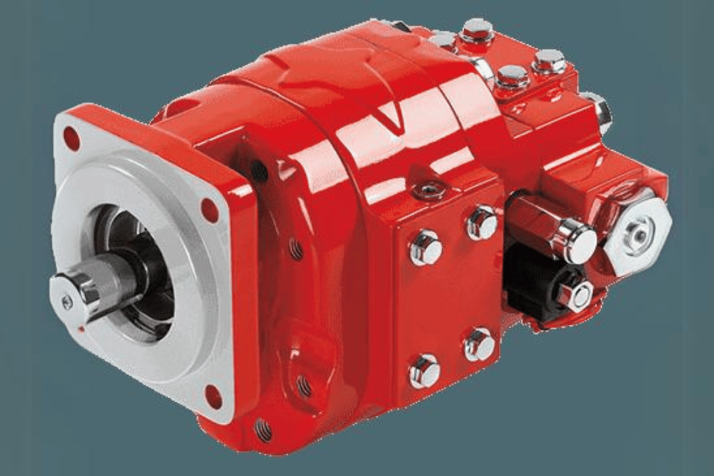
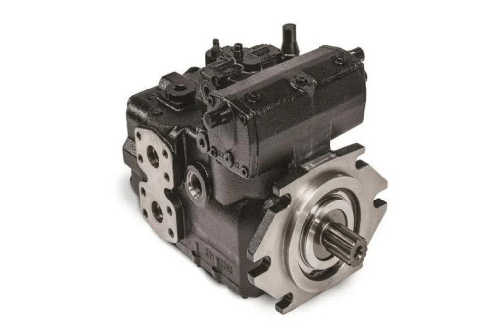
A hydraulic pump is a device that changes mechanical energy into liquid power by using the movement and force of fluid. These devices are necessary in hydraulic systems, which means they compress fluids to send power to different kind of actuators like motors or cylinders. Usually run by either electric motors or internal combustion engines (IC), these types of pumps create an empty space from which they draw off hydraulic fluid out of a tank. When in use, it then forces this same liquid into the closed system thus enabling control over speed as well as directionality while moving things. The potential energy contained within the liquid can be used for various tasks, including lifting heavy objects during construction work or driving machines at factories, among others. Therefore, anyone working in industries powered by hydraulics needs to know how these pumps function and their operational techniques.

Basic Functioning of a Hydraulic Pump

Hydraulic pumps are machines designed to convert mechanical energy into hydraulic energy through the movement of fluids, therefore producing force. Below, I will explain how they work and their basic principles.

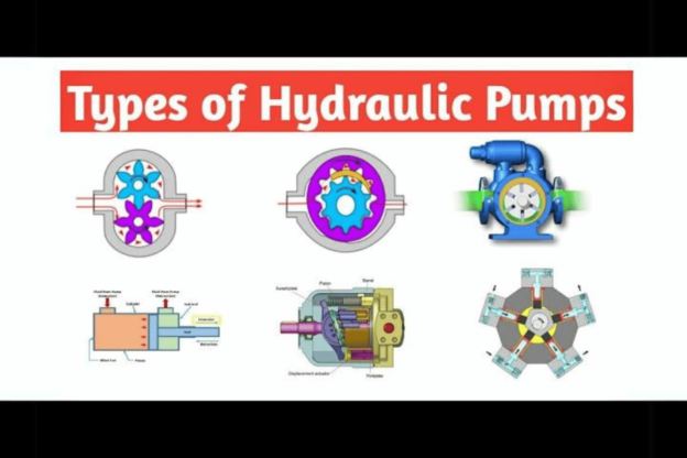
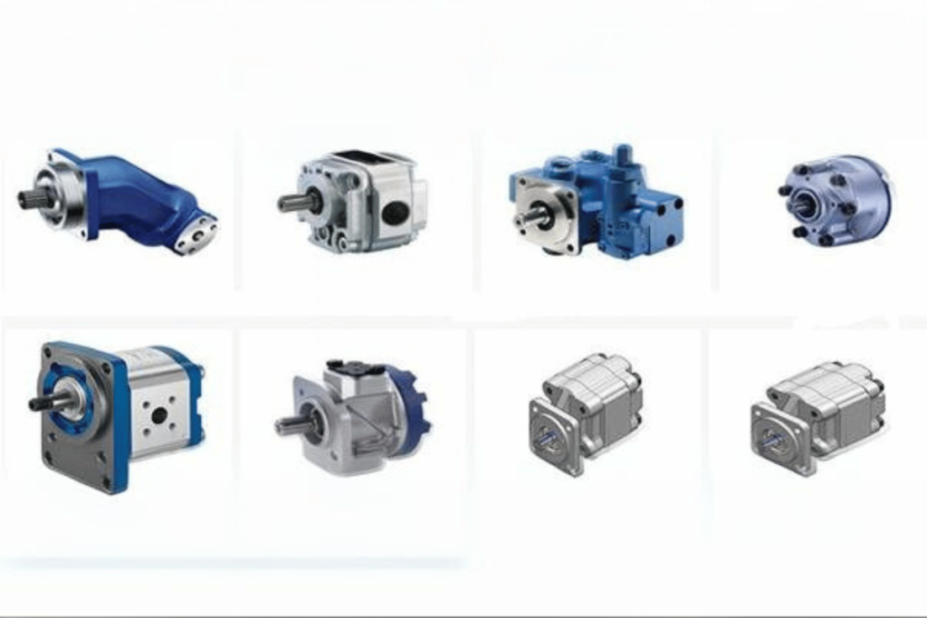
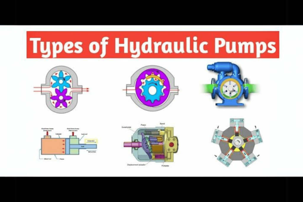
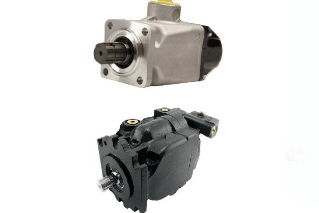
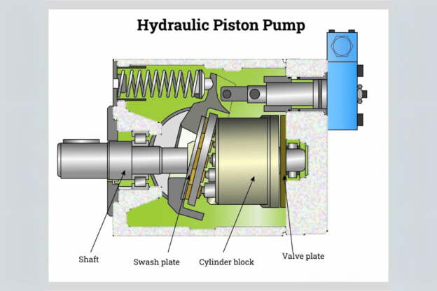
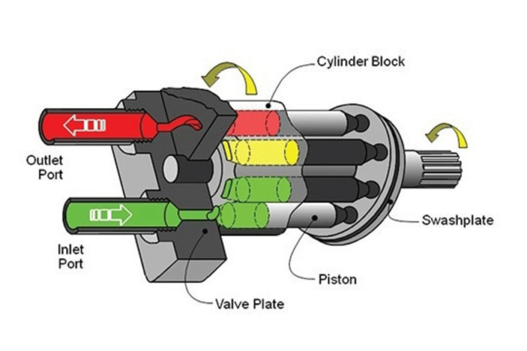
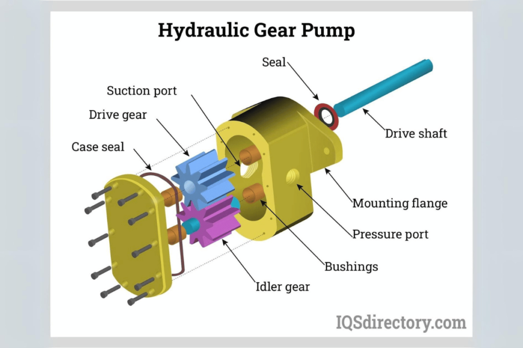
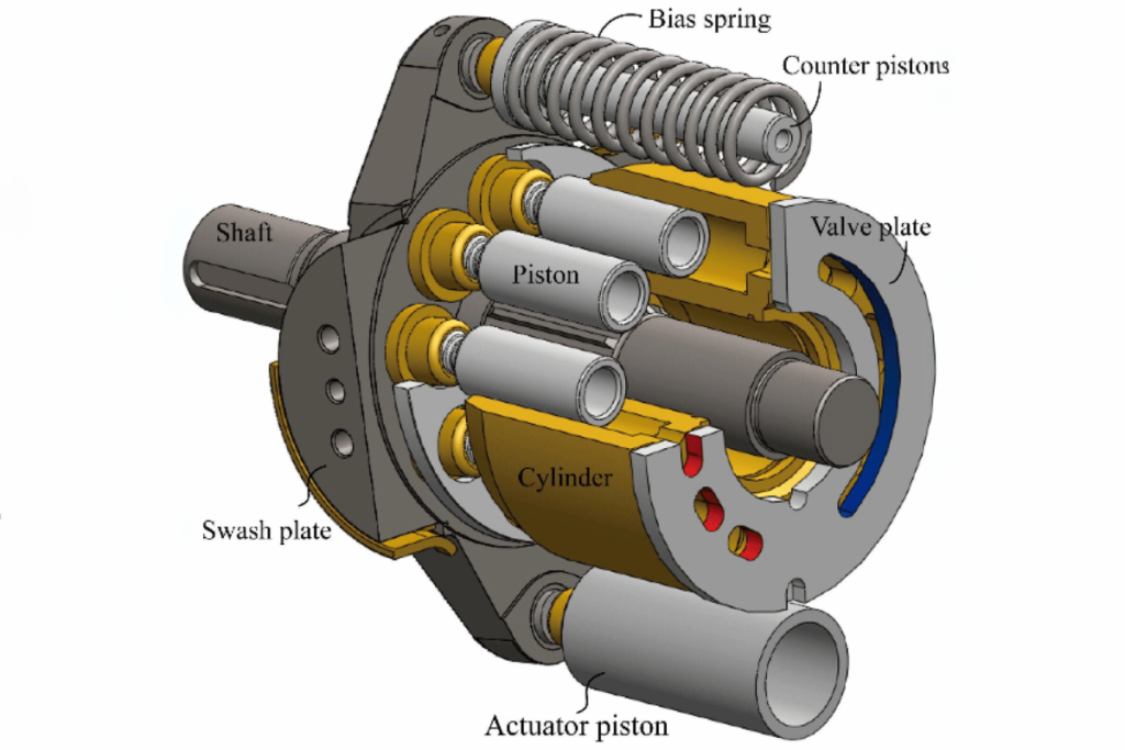
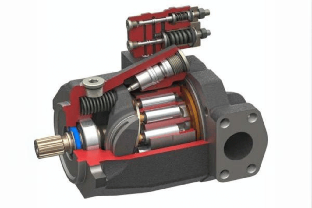
  1. Common Types: Gear pumps, piston pumps, and vane pumps are three examples of commonly found hydraulic pump designs. Each one works differently – gear pumps use rotating gears; piston pumps employ reciprocating pistons; sliding vanes move the fluid in vane pumps.
  2. Pressure Creation: Pressure is produced in hydraulic pumps by transferring liquid from an area with low pressure to another with higher pressure. This generated force enables lifting heavy objects or moving loads around.
  3. Rate of Flow: Flow rate is expressed as litres per minute (L/min) or gallons per minute (GPM), and represents the volume of fluid that can be displaced by a pump during one unit time. More power may be needed for higher flow rates which can improve efficiency but not always necessary.
  4. Displacement: Displacement measures how much space within an object occupied by matter moves when acted upon by external forces such as heat or pressure changes. It is typically given in cubic centimeters (cc) or liters – this value shows what amount goes through each cycle of the machine thereby indicating capacity for applications where it might be used most suitably.
  5. Efficiency: Hydraulic pump efficiency varies depending on design factors and operating conditions under which they work best. How well input energy is converted into fluid flow is referred to as volumetric efficiency, while mechanical efficiency refers to parts where losses could occur due to frictional forces, among other things.
  6. Power Requirement: The power required for a hydraulic pump can be determined using the formula ( P = \frac{Q \times P}{600} ), where ( P ) stands for power in kilowatts; ( Q ) denotes flow rate measured in liters per minute; and ( P ) represents pressure measured in bars. Knowing power requirements aids in proper motor selection as well as system sizing.
  7. Temperature Range: Hydraulic systems work optimally when fluids are kept within certain temperature limits, usually 20°C to 60°C (68°F − 140°F). This is because efficiency decreases outside this range and such extremes could also cause damage.
  8. Suction & Discharge Conditions: Cavitation—a phenomenon that can lead to severe destruction if left unchecked—must be avoided by maintaining sufficient inlet conditions. Discharging should meet the requirements of the overall setup for effective functioning.

These considerations highlight the necessity of choosing an appropriate hydraulic pump for particular tasks so as to achieve maximum efficiency, dependability and safety in any given application involving hydraulics.

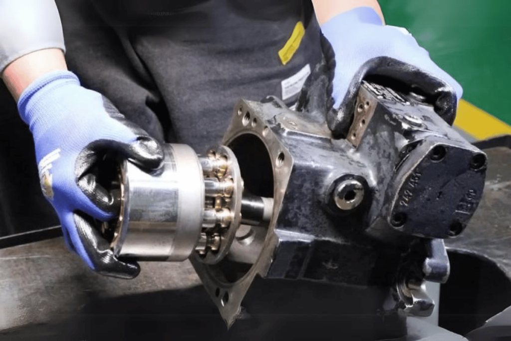
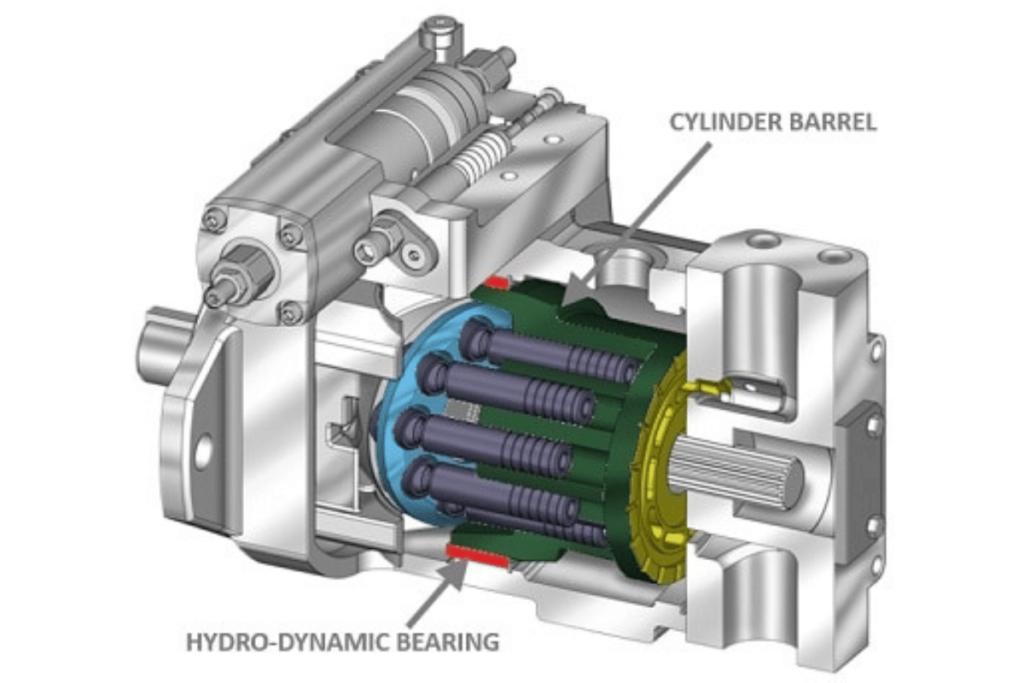
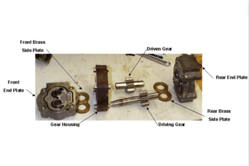
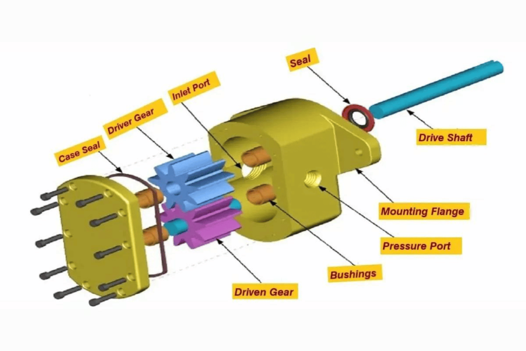
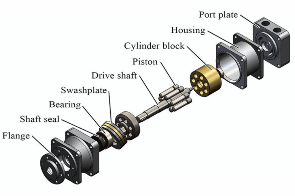
Critical Components of Hydraulic Pumps

Hydraulic pumps contain numerous elements that cooperate in order to convert mechanical energy into hydraulic energy. Comprehending these parts and their functions is crucial for effective pump operation. I will list the main components below:

  1. Pump Housing: The outer covering encompasses all inner constituents and maintains system integrity under operational pressures. The material selection and design should withstand an application’s specific pressure requirements.
  2. Drive Mechanism: Usually, an electric motor or an internal combustion engine provides the rotational power required for running a pump. The motor’s power output must match the pump’s power demand to achieve the best performance.
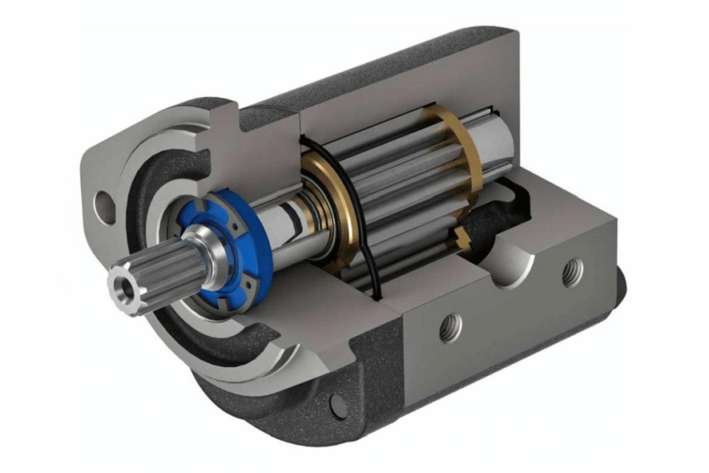
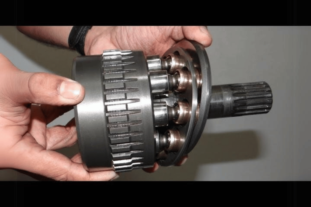
  3. Rotating Group: This includes the rotor, cam, or impeller (depending on the type of pump) responsible for creating fluid flow. The design used in this group directly influences a pump’s flow rate and displacement.
  4. Suction and Discharge Ports are openings through which fluids enter into or exit a pump. Proper sizing and positioning are essential for efficient fluid transfer while minimizing losses due to turbulence.
  5. Seals and Bearings: They prevent leakage and reduce friction, thereby improving efficiency as well as prolonging the life span of pumps. The material choice should be guided by the hydraulic fluid type and operating conditions.
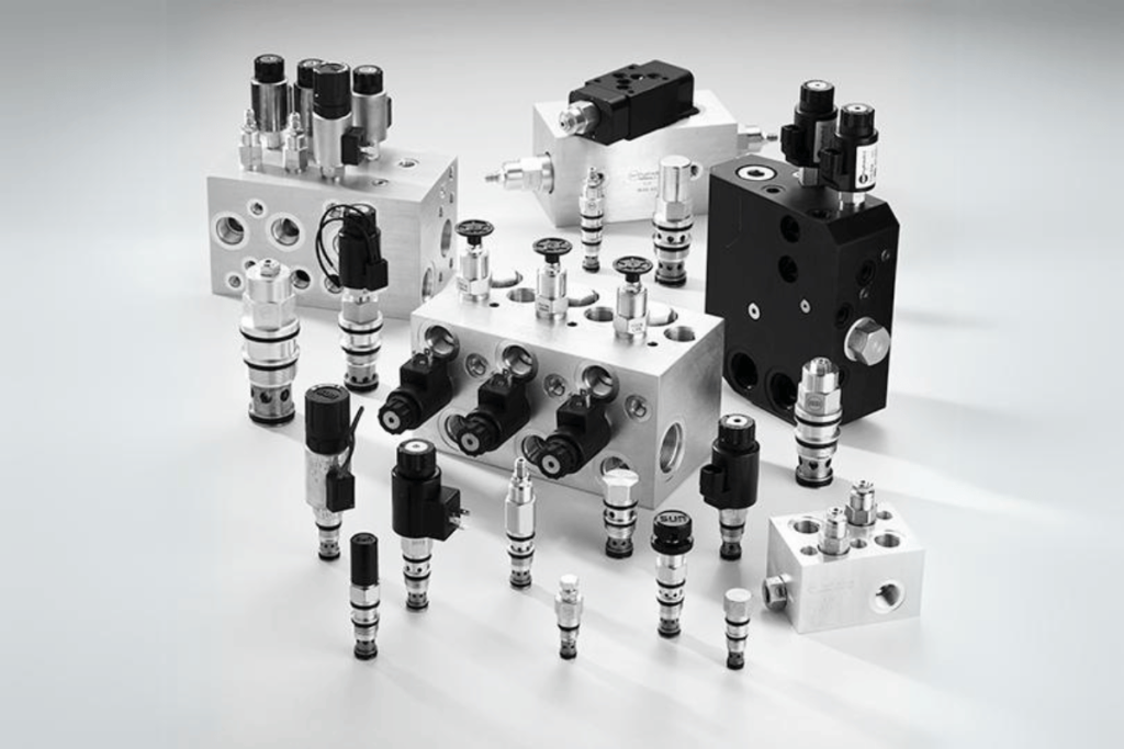
  6. Control Valves: These regulate flow rate and pressure within the hydraulic system, thereby ensuring that a given pump does not exceed safe operation limits. System performance requires calibration of these valves.
  7. Filters: They play a vital role in removing contaminants from hydraulic fluid hence protecting pump parts against wear or damage caused by such particles. The selection of filters ought to be based on properties exhibited by the fluid being filtered plus the environment where it operates.
  8. Reservoir: It refers to storage tank for holding hydraulic fluids which supplies both pumps together with associated systems; size & design should make allowances for expansion/return flow rates exhibited by these fluids during use.
  9. Sensors and Gauges: Used for monitoring different operational parameters like pressure, temperature and fluid level etc., such instruments offer valuable insights that can prevent equipment failure.
  10. Cavitation Prevention Features: These are components like vortex inhibitors or special intake designs that help minimize cavitation risk, thereby safeguarding the pump against potential harm from vapor bubble formation.

Understanding these parts and their relation is crucial when selecting hydraulic pumps for different applications. Hydraulic systems ensure reliability and efficiency through the choice of materials, designs, and configurations based on operating conditions and expected performance parameters.

The Role of Hydraulic Systems

Hydraulic systems are used every day in many industries where power is transmitted and controlled using a fluid under pressure. Such systems can be found in construction, manufacturing, aviation as well as automotive applications among others. However, efficiency within hydraulic systems largely depends on some technical considerations which include:

  1. Pressure Rating – This refers to the safe working limit in pounds per square inch (psi) of a hydraulic system commonly ranging between 1500-3000 psi for standard systems while some high-pressure applications may exceed 5000 psi.
  2. Flow Rate—It indicates how much fluid can pass through the system and is measured in gallons per minute (GPM) or liters per minute (LPM). Typical flow rates vary across various industries, with industrial applications ranging from 10 to 50 GPM.
  3. Viscosity Of Hydraulic Fluid – It shows how thick or thin the liquid is usually measured in centistokes (cSt). The recommended viscosity range is between 15 – 68 cSt depending on temperature and application.
  4. Temperature Range—Hydraulic fluids work best within the temperature range of -20°F to 200°F (-29°C to 93°C), considering the type used and ambient conditions. This factor may affect the performance of the fluid itself and the overall efficiency of a system.
  5. Power-To-Weight Ratio—This ratio determines what amount of output power can be expected from a given weight, affecting design considerations for mobile units like excavators and lifts.
  6. Tolerance Levels: These indicate allowable deviations between different parts or connections that could affect reliability or performance; typically precision tolerances fall around 0.005″-0.010″ for critical components.

Considering these parameters allows professionals in any industry to select appropriate hydraulic systems for their specific operational needs, guaranteeing higher performance levels alongside durability. Consequently, closely examining these factors together with how various parts interact with each other within the system might lead to increased efficiencies, thus lowering operational costs.

How to Safely Adjust the Pressure on a Hydraulic Pump

how to adjust pressure on hydraulic pump

Altering the force on a hydraulic pump is an important operation that must be done carefully for safety and machine integrity. Here’s what you need to do:

  1. Operator’s Manual Review: Always read the operator’s manual of the specific hydraulic pump you’re using to learn how the manufacturer recommends adjusting pressures.
  2. Safety First: Prioritize your safety by wearing appropriate personal protective equipment (PPE) such as gloves and safety goggles. Clear the working area from any hazards.
  3. Switch Off the Machine: To prevent accidental activation, the hydraulic pump pressure should be adjusted only when the system is not running.
  4. Identify Pressure Adjustment Screw: You can see this valve or screw at some point on your pump; usually it has an indicator sign. This is what alters pressure settings.
  5. Get a Pressure Gauge: Fit a pressure gauge somewhere in line with your hydraulic system for accurate monitoring of pressure levels. This will enable better adjustment targeting.
  6. Gradual Modifications: Decrease or increase pressure slowly by turning adjustment screws – little adjustments are recommended so that you check every time not to overshoot desired pressure.
  7. Leaks Checkup: Once all changes have been made, look for any leakages around connections that may have been caused during the alteration process; fix them before using the machine further.
  8. Test Run: Restart your pump and watch the pressure gauge to confirm if it can maintain the desired levels under operational conditions.
  9. Record Amendments: Document all corrections made and why they were made; this keeps history of operations & provides future reference points

Following these steps will enable you to carry out a risk-free shift in force applied to a liquid transmitting device while ensuring the durability and trustworthiness of the equipment.

Preparation and Safety Precautions

Preparation and safety are the most critical aspects of hydraulic systems, and they must be prioritized. Here are some of the precautions you should take into consideration:

  1. Wearing Personal Protective Equipment (PPE): Put on necessary PPE like gloves, safety glasses or steel-toed boots in order to protect yourself from hydraulic fluid splashes and mechanical injuries.
  2. Knowledge and Competence: Hydraulic machines should only be operated by people who have been trained well enough to handle them; otherwise, they can cause a lot of harm. Safe adjustment requires one to read through the operating manuals of the machines to familiarize themselves with various parts that may require adjustment accordingly for safety reasons.
  3. Equipment Checkup: Before making any changes, always inspect all parts of a given system for mechanical problems, such as leaks, that arise from wear and tear over time.
  4. Organizing Workspace: One should keep their working area clean whenever dealing with anything, whether hydraulics or not. Clutter can easily lead to accidents especially slips and falls hence should be avoided at all costs.
  5. Emergency Measures: Understand how emergencies are handled; this includes shutting down systems fast enough plus accessing first aid if need be.
  6. Isolating Power Sources: Make sure power sources have been isolated before any adjustments are made where applicable, then lock machinery in an off position so that there is no chance of it getting activated without warning, thereby causing harm inadvertently.
  7. Relief Valves Setting: One should always wait until pressure has dropped entirely since immediate release could lead to self-inflicted injuries caused by sudden energy discharge.
  8. Effective Communication: When maintenance activities are carried out within teams, clear channels ought to exist that facilitate proper information sharing, thus averting misunderstandings between different parties involved.

By following these guidelines on preparation and safety, risks associated with working on hydraulic pumps will be reduced while operational efficiency will increase. Always remember that safety is an ongoing process that requires one to stay alert and follow best practices at all times.

Using a Pressure Relief Valve

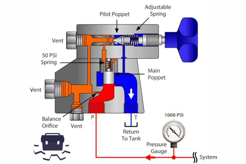
In hydraulic systems, pressure relief valves are crucial for safety since they prevent the build-up of too much pressure. If the internal pressure goes beyond a predetermined threshold, this valve opens by itself, allowing fluid to escape, thus saving the system from possible damage. Below is a short review about pressure relief valves with information from different reliable sources:

1. Operations: The basic role of any PRV is to protect hydraulic systems from overpressure situations. This prevents failure of equipment and ensures security for operators.

2. Setting Parameters:

  • Opening Pressure – The setting value for opening pressure should be determined correctly; usually given in psi (pounds per square inch) as stipulated by the system requirements.
  • Flow Capacity—It must be able to handle the highest flow rates in gallons per minute (GPM) so that it can appropriately accommodate pressure spikes.

3. Types of Pressure Relief Valves:

  • Spring–loaded Valves are commonly used, in which a spring holds the valve seat closed until system pressure exceeds spring tension.
  • Pilot Operated Valves – They work with higher flows and use pressure from the system to pilot the opening and closing of this valve

4. Installation Guidelines

  • Orientation: Ensure you install it vertically thus ensuring reliability in its operation.
  • Close Proximity: Place it near the point where your pressures come from within your setup so as to reduce potential lag time during response due to changes in levels around different parts of an installation etcetera

5. Maintenance Recommendations: Such devices should be regularly checked by testing them periodically, even when not needed, to make sure that everything is working fine as expected. These things can wear out easily or fail without any warning signs displayed, which might greatly affect how well they perform their tasks.

Understanding technical parameters and operational principles related to these facilities may help improve safety standards while using hydraulic machinery. Always consult the manufacturer’s instructions whenever making adjustments or settings

Step-by-Step Guide to Adjusting Pump Pressure

The pump pressure needs to be adjusted to be successful and safe in hydraulic systems. Here are some steps that can be taken together with corresponding technical parameters taken from trusted sources:

  1. Recognize the Required Pressure: Identify the best working pressure by considering different system requirements and manufacturer specifications. Usually measured in psi (pounds per square inch), it should match the design parameters of your hydraulics.
  2. Find where the Pressure Adjustment Mechanism Located; Most pumps have a screw or knob used for adjusting pressures, this part can be located anywhere depending on type or model of a pump.
  3. Use Pressure Gauge: Before any changes are made, one must connect a calibrated pressure gauge. This will help you monitor the current level of pressure within the system and ensure that such data will aid in achieving the desired results after adjustment.
  4. Increase/Decrease Setting – Increase Pressure: This can be done by turning the adjustment mechanism clockwise to raise the working thresholds.- Decrease Pressure: Counterclockwise should be turned to lower those limits, but make sure you make slight adjustments at a time so as not to go beyond what was intended.
  5. Check for Leaks—After making an alteration, check for signs of leakages around connections (fittings) and joints (seals). A leak-free environment must always be maintained for safety reasons and performance enhancement purposes.
  6. Test The System—Once these changes have been effected, carry out a test run on the system at the new pressure setting and observe its behavior during operation.
  7. Record Changes—Document recorded observations about testing done and setting applied on pressures somewhere so that they may act as a future reference point while undertaking maintenance activities.
  8. Regular Review– Regularly review pump’s pressure levels by checking them against wear over time or any other alterations due shifts within needs of given systems.

Technical Parameters To Note:

  • Setting Range – minimum-maximum ratings required by specific application
  • Flow Rate – ensure compatibility between pump size vis–vis gallons per minute (GPM) required for particular systems.
  • Temperature ConsiderationsOperating temperature ranges should be considered because extreme heat or cold can affect pressure readings and pump performance, too.

If you follow these steps carefully and consider the technical parameters, you will be able to adjust the pump pressure effectively to improve the performance and reliability of your hydraulic system.

Tools and Equipment Needed for Pressure Adjustments

how to adjust pressure on hydraulic pump

Several tools and equipment must be collected before adjusting a hydraulic pump’s pressure effectively. Here are some of them:

  1. Pressure Gauge – A dependable gauge for accurately measuring the system’s pressure as modifications are being made.
  2. Wrenches and Socket Sets – These are required in order to loosen/tighten connections or adjust screws on the pump.
  3. Screwdrivers – Different types (flathead, Phillips) may be needed for various parts.
  4. Adjustment Tool(s) – Depending on its design there might be a special tool/wrench that is used specifically for it where you can adjust your screw about how much force should come out from this unit .
  5. Pliers – These can come in handy when you need to grip hoses tightly so they don’t move around while working with other parts
  6. Leak Detection Solution – Soap solution will help identify if there are any leaks at connections after making adjustments
  7. Safety Gear – Use gloves or wear goggles; personal protective equipment is important during all processes like these ones
  8. Hoses & Adapters – You might have to use some additional hoses or adapter fittings so everything fits together correctly with the pressure gauge
  9. Measuring Tape – It’s always good practice to carry one around just in case you need it for any measurements during setup or adjustment stages
  10. Documentation Tools – Have either a notebook or electronic device ready where changes made can be recorded too quickly, thus keeping records straightforward.

If all these things are readily available then adjusting pump pressure should not take much time but also keep up safety measures .

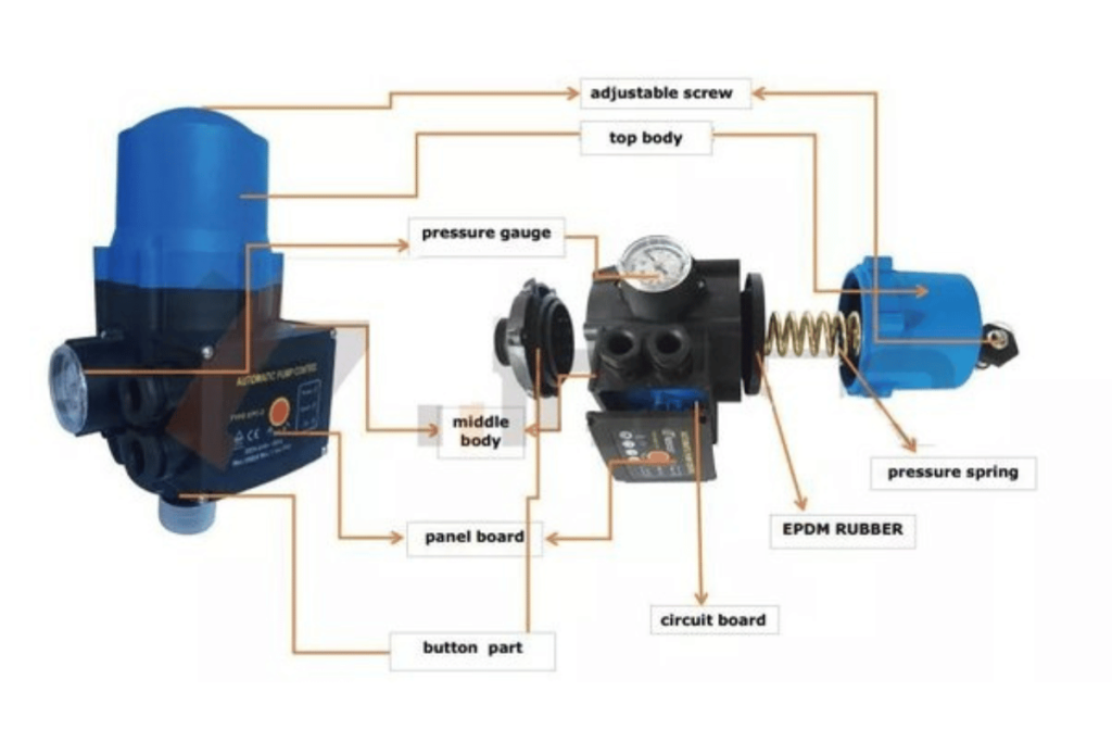
Pressure Gauge and Its Importance

A pressure gauge is necessary to measure the pressure in a hydraulic system accurately. It is essential to understand the pressure for many reasons:

1. Efficiency of the System: Energy-saving and peak performance are achieved when the hydraulic system maintains the right pressure.

2. Security: Too much pressure can cause equipment breakdowns and create dangerous situations like leaks or explosions; therefore, operators should be able to check their levels using this device since it allows them do so before any problem occur.

3. Proactive Maintenance: A hydraulic system can be checked often to detect areas where parts have worn out or failed to function properly. By using these readings, time can be saved by fixing things early enough instead of waiting until they break down completely.

4. Technical Parameters: Some of these include;

  • Pressure Range: minimum and maximum pressures that may be measured accurately by a gauge, usually expressed in psi, bar, or Pa.
  • Accuracy—how correct the indicated pressure is compared with the actual one, usually shown as a percentage of the full scale (e.g., ±1% FS).
  • Connection Types – different thread sizes, such as 1/4″, 1/2″ among others, together with fitting types NPT or BSP, which determine the connection between this instrument and the hydraulic system being serviced.
  • Material Compatibility – gauges should always be made from stainless steel if corrosive substances are going to pass through otherwise, they might get damaged easily due to chemical reaction caused by fluids involved during operation

In summary, without a doubt, those machines cannot work safely or efficiently unless controlled through sound monitoring systems, which prevent overloading them beyond given limits and also keep all other factors constant. For example, suppose we did not have these meters, what could happen? Clearly speaking everything will go haywire because nobody will know how much force is being generated at different points within the circuitry. Additionally, what if some parts wear out or fail? This statement implies that no maintenance activity would occur since no one can detect such failure signs beforehand until they manifest themselves, thus leading to the breakdown of all components connected as per design.

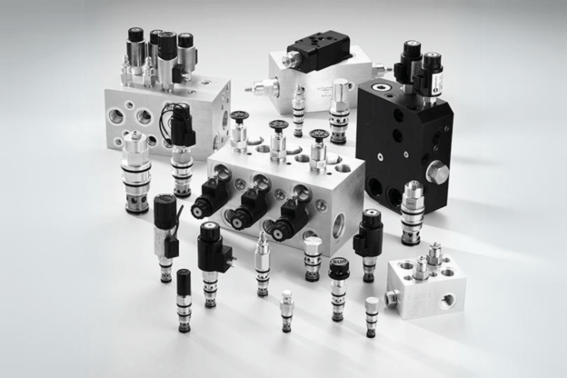
Types of Flow Control Valves

Flow control valves are essential parts of the hydraulic system which regulate fluid flow rate for maximum performance and efficiency. Here are some types of flow control valves and their main technical specifications:

1. Needle Valves:

  • Function: It gives accurate control over flow due to its tapered shape.
  • Pressure Range: Usually designed for moderate pressure applications up to 3000 psi.
  • Connection Types: Available in different sizes (1/4”, 1/2”) with NPT or BSP connections.

2. Ball Valves:

  • Function: It enables quick shut-off by rotating a ball within the valve to control flow.
  • Pressure Range: Normally handles pressures up to 1500 psi.
  • Accuracy: Very little leakage, typically rated at ±0.1% of flow rate.

3. Gate Valves:

  • Function: Designed for on/off service rather than throttling; gate can be fully opened or closed.
  • Pressure Range: Can withstand high pressures usually above 2000 psi.
  • Material Compatibility: Often made from stainless steel or brass for corrosive environments.

4. Throttle Valves:

  • Function: Intended for speed control by reducing the flow rate mechanically.
  • Pressure Range: Effective in low-pressure to moderate-pressure systems.
  • Technical Parameters: Frequently provided with means for adjusting flow restriction.

5. Check Valves:

  • Function: Restricts backflow in a system by allowing flow in one direction only
  • Pressure Range: Available for different systems, often up to 3000 psi
  • Connection Types: Regular fittings are usually one inch or more extensive with NPT connections

6. Solenoid Valves:

  • Function: They are electrically operated and used when precise flow control is required
  • Pressure Range: Typically rated from 50 psi up to 150 psi
  • Accuracy: Response times are typically less than 1 second providing fast controls

7. Flow Control Regulators:

  • Function: Maintains constant preset flow despite pressure changes
  • Pressure Range: Can handle pressures ranging between 5psi –150psi
  • Accuracy: Flow stability within ±5% variance

8. Proportional Valves:

  • Function: These valves provide flow or pressure control proportionally to input signals
  • Pressure Range: Usually rated for systems up to 3000 psi
  • Technical Parameters: They have hysteresis and linearity specifications for precise response.

9. Variable Orifice Valves:

  • Function: Controls flow by adjusting orifice size
  • Pressure Range : Versatile across various applications usually below 1500 psi
  • Material Compatibility: Made with materials suitable for controlled media

10. Directional Control Valves:

  • Function: Guides fluid movement within a system often with multiple flow paths available
  • Pressure Range: Usually rated up to 3000 psi
  • Connection Types: Typically, multiple ports can accommodate different fittings based on system design requirements.

Each valve performs a specific function in controlling the flow, and knowing these parameters is necessary when selecting hydraulic system valves for safety, efficiency, and reliability.

Other Essential Tools

Several other key tools should be used when working with hydraulic systems to improve performance and maintenance. The following instruments are commonly featured on the top ten websites with their specifications mentioned:

1. Gauges for measuring pressure:

  • Function: They measure fluid pressure in a system.
  • Pressure Range: Typically 0 – 6000 psi
  • Accuracy: Normally ±1% of the full scale ensures accurate readings, which is crucial for the safety and integrity of the whole system.

2. Flow meters:

  • Function: Used to determine flow rate of liquids or gases
  • Flow range: Usually between 0.1-500 GPM though this can vary widely.
  • Accuracy: Generally ±2% of reading required to keep desired flow rates constant.

3. Hydraulic hose assemblies:

  • Function: Transmits hydraulic fluid within the system
  • Pressure rating: Ranges from 3000 psi up to 6000 psi depending on application
  • Temperature limits: Usually rated from -40°F through 212°F hence suitable for wide range environmental conditions .

4. Filtration systems:

  • Function: They remove contaminants from hydraulic fluid.
  • Filtration rating : Commonly stated as either 10 microns or finer so as to achieve optimum cleanliness levels for the liquid being used in this case oil would work best if it were clean enough .
  • Flow rateIt can be anything between 5 GPM and over 100 GPM, depending on what the system needs at any given time.

5. Torque wrenches :

  • Function: To ensure connections are appropriately tightened thus preventing leaks.
  • Torque range: Normally between10 ft-lbs and150 ft-lbs depending on application needs
  • Accuracy: Usually ±3% of setting necessary for achieving good seal integrity.

6. Seal kits :

  • Function: Keeps hydraulic components sealed against leakage
  • Material types: These include Nitrile, Viton , polyurethane etc chosen according to fluid compatibility and temperature requirements
  • Pressure ratings: Must match maximum pressure within the system, which could be 3000 psi.

7. Hydraulic jacks:

  • Function: They use hydraulic fluid pressure to lift heavy objects.
  • Lift capacity: Typically rated between 2 tons -50 tons
  • Stroke length: Varies but usually between 5”-12” for versatility when lifting various loads.

8. Pneumatic tools :

  • Function: Employed where pneumatic power is advantageous
  • Pressure rating: operates typically at about 90 –120 psi
  • CFM requirements: Flow rates often needed range from 4-10 CFM depending on the tool.

9. Leak detectors :

  • Function: Used to find leaks in hydraulic systems to keep them safe and efficient.
  • Sensitivity: It usually detects gases as low as one part per billion, which is paramount when it comes to preventing catastrophic failures.

10. Maintenance software:

  • Function: Monitor and maintain hydraulic system performance and scheduling
  • Features: Uptime tracking, predictive maintenance alerts, fluid analysis capabilities for better overall reliability.

These tools if used together with appropriate technical parameters will ensure that hydraulic systems operate safely and efficiently. The correct selection and care of these instruments will improve any given system’s life expectancy and performance.

Tips for Maintaining Optimal Hydraulic Pump Pressure

how to adjust pressure on hydraulic pump

To keep your hydraulic pump at its best pressure, here are some suggestions:

  1. Inspect Components Often: Regularly inspect hoses, seals, and fittings for signs of wear or damage. Replacing broken parts can prevent loss of pressure.
  2. Fluid Level Monitoring: Monitor hydraulic fluid levels and ensure they stay within the range recommended by the manufacturer so that pressure remains steady.
  3. Clean up: The hydraulic fluid should be clean and free of dirt or other contaminants. Use appropriate filters to prevent debris from entering the pump and causing it to wear out.
  4. Find Leaks: Periodically perform leak tests on all systems; even small ones can drop pressure significantly over time.
  5. Pressure Setting Adjustment: Check pressures occasionally and adjust them as necessary for optimum performance based on operational requirements.
  6. Maintaining Proper Temperture: Ensure that hydraulic fluid is maintained at the correct operating temperature; overheating can lead to breakdowns and unreliable pressure readings.
  7. Regular Monitoring Of Pressure: Employ a system pressure monitoring device equipped with a gauge which should be checked often for any changes that could suggest problems within the system
  8. Stick With The Manufacturer’s Guidelines: Comply with service interval recommendations established by manufacturers and other maintenance instructions provided in their manuals to prevent premature failures.
  9. Only use Quality Fluids: Invest only in high-quality hydraulic fluids meant for your specific pump model which meet or exceed required specifications.
  10. Staff Training & Awareness Creation: Make sure everybody who operates any machine understands how best they can manage such systems without causing pressure problems due to misuse

With these tips, one can ensure their hydraulic system remains intact, thereby providing dependable service and extending the equipment’s life span.

Regular Inspection and Maintenance

To ensure that a hydraulic system lasts long and functions well, it is essential to have regular check-ups and servicing. Here are a few things you can do as supported by studies from different sources:

  1. Scheduled Inspections: These should be done every three to six months, depending on how much the system is being used and the environment under which it operates. They involve checking whether hydraulic fluid is needed and whether there are any worn-out hoses or leaks in connections related to fittings.
  2. Filter Replacement: Change filters within 500-2000 running hours or at least once per year as recommended by the manufacturer because dirty ones can rapidly increase contamination levels, thus reducing the whole system’s efficiency.
  3. Fluid Analysis: Ensure that routine fluid analysis tests are carried out to detect signs of contamination and decay early enough. The key parameters to be tested using ASTM methods should include particle count and moisture content, as well as viscosity, where hydraulic fluids generally require a minimum of 100 VI (Viscosity Index).
  4. Heat Exchanger Care: Check heat exchangers for blockages regularly and clean them accordingly. Overheating leads to fluid breakdown, which may fail; hence, it is necessary to always maintain a temperature between 40°C and 60°C (104°F 140°F) or thereabouts.
  5. Seal Integrity Check: Always inspect seals and o-rings frequently, mainly looking for wear signs. This will prevent fluid loss through leakage points, thereby reducing overall operational efficiency. Replace those showing fatigue symptoms immediately.
  6. Pressure Checks: Regularly measure pressure levels within the range stated by manufacturer during design like 1000 – 3000 PSI (Pounds per Square Inch) depending on application; otherwise any significant deviation could prove costly later on.

If records about maintenance activities are kept well, these steps will help improve the reliability of your hydraulic systems while also reducing risks.

Monitoring System Pressure

Monitoring the pressure of a system is necessary for hydraulic systems to work efficiently. It ensures that the system operates within prescribed limits thus preventing failures and maximizing performance. Here are things to consider about monitoring system pressure:

  1. Ranges of Operating Pressure: While this may vary depending on the application, most hydraulic systems work under 1000-3000 PSI. Continuously monitoring this bracket helps detect leakages or blockages at their initial stages.
  2. Gauges for measuring Pressure: Real-time monitoring requires the use of correct gauges that give true readings; hence, accuracy is paramount. Digital types with ±1% full-scale accuracy are preferred because they are more reliable.
  3. Alarms: Setting up alarm systems that alert when pressure goes beyond specific points can significantly reduce hazards. Normally, thresholds are put at 10% above or below normal operating pressures.
  4. Logging Data: Proactive maintenance strategies can be adopted if trends are identified through regular logging of pressures recorded over time. This involves noting fluctuations in pressure indicative of wear and tear on components.
  5. Reports on Maintenance: Frequent review and analysis of maintenance reports can help identify areas for improvement. Records indicating repetitive deviations from recommended pressures will show exact problems, such as failed seals or blocked lines.
  6. Environmental Considerations: Temperature and external loads among other environmental factors affect readings taken while measuring pressures. Therefore, hydraulic fluid should be kept at temperatures ranging from 40°C to 60°C (104°F-140°F) so that viscosity remains within operational limits for optimum performance.

Following these tips together with frequent checks will ensure reliability and efficiency in terms of energy utilization by the machines used in industries. This will lead to longer working lives and fewer breakdowns of such equipment, thereby reducing production losses caused by machine failure during the manufacturing process.

Addressing Pressure Fluctuations

To tackle pressure fluctuations in hydraulic systems adequately, we must identify common causes and apply appropriate remedies. Here are some things to consider based on what is currently believed to be best practice:

  1. Causes Identification: Pressure fluctuations may arise from different sources, such as problems with pump performance, valve failures, or leaks within the system itself. Conduct thorough examinations to determine the root cause.
  2. Pump Selection: Ensure that the size of the selected pump matches well with its intended application range. Operating beyond design limits could make it unstable i.e variable displacement pumps can dynamically vary flow rates to reduce pressure changes.
  3. Flow Control Valves: Use flow control valves strategically to efficiently manage fluid movement throughout the entire system. Sizing should always be carried out, taking into consideration the maximum flows required by a given setup, which are usually expressed in terms of GPM (gallons per minute) or LPM (litres per minute).
  4. Fluid Quality: Fluid cleanliness ought never to be overlooked. ISO cleanliness standards (e.g., ISO 4406) provide a basis upon which one can determine acceptable contaminant levels known to affect consistency in pressures.
  5. Accumulators Utilization: The incorporation of hydraulic accumulators assists greatly in dealing with pressure fluctuations. They should be sized and precharged according to operational needs, typically represented by bar/psi readings.
  6. System Layout: The layout of any given hydraulics system needs to be looked at critically so as not have too many bends or restrictions along the piping route because sharp turns induce turbulence which causes drops/spikes in pressure
  7. Monitoring Technologies: Advanced monitoring technologies, such as real-time pressure monitoring and feedback systems, help make instant corrections whenever deviations occur.
  8. Preventative Maintenance: Regular preventive maintenance checks are needed; hence, a schedule should be developed based on either hours worked or conditions observed, considering all necessary replacements after inspection.

Implementing these measures while closely watching how the equipment performs will help operators reduce their exposure to risks linked to pressure fluctuations within hydraulic systems, thereby guaranteeing efficiency and a prolonged life span of the equipment.

Frequently Asked Questions (FAQs)

how to adjust pressure on hydraulic pump

1. What causes pressure fluctuations in hydraulic systems?

Pressure fluctuations can result from several factors, including changes in fluid flow, temperature variations, leaks, or rapid changes in actuator speed. Proper system design and component selection are essential in minimizing these fluctuations.

2. How often should preventative maintenance be conducted on hydraulic systems?

Preventative maintenance should be scheduled based on operational hours or the system’s condition. Generally, regular inspections every 3 to 6 months are advisable to ensure that components function correctly and identify potential issues early.

3. What are the benefits of using hydraulic accumulators?

Hydraulic accumulators help absorb shocks, reduce pulsations, and maintain system pressure. By dampening pressure fluctuations, they enhance hydraulic systems’ efficiency and reliability.

4. How can I determine the appropriate size for flow control valves?

The appropriate size for flow control valves should be based on the system’s maximum flow rate requirements, typically calculated in gallons per minute (GPM) or liters per minute (LPM). Consulting with valve manufacturers or hydraulic system design specialists can also provide guidance.

5. What is the importance of fluid cleanliness in hydraulic systems?

Maintaining high fluid cleanliness is essential to prevent contamination that can lead to component wear, increased maintenance costs, and system failures. Adhering to ISO cleanliness standards can help ensure fluid quality and system longevity.

how to add a hydraulic pump to a tractor

Adding a Hydraulic Pump to Your Tractor: Step-by-Step Guide for Boosting Your Tractor’s Functionalities

Efficiency and versatility are of great importance in the field of farming, especially if it involves productivity in large scale. One way to increase your tractor’s efficiency is by fixing a hydraulic pump. This guide will take you through the process of integrating a hydraulic pump into your tractor step by step; hence, giving you both practical and insightful knowledge necessary for optimizing its functionality. This may be required when powering loaders with implements or improving overall performance on a farm machine; therefore, all that is needed for such modifications can be found in this text. Let us dive deep into what every farmer should know about hydraulics and how these systems will benefit their operations at large.

Why Would You Want to Add a Hydraulic Pump to Your Tractor?

how to add a hydraulic pump to a tractor

Adding a hydraulic pump to your tractor can have many benefits that will significantly improve farming operations. First, it increases the flexibility of tractors by enabling them to drive different types of equipment, such as loaders, backhoes, or planters, thus broadening their functions beyond towing alone. Secondly, hydraulic systems offer better lifting and digging power which may enhance efficiency and reduce field time for task completion. Also, these pumps provide smooth control thereby allowing accurate adjustments when dealing with heavy loads. Finally, integrating this technology can enhance overall productivity in farming where multiple machines were needed before but now some tasks can be performed using one tractor fitted with appropriate attachments. In short these improvements save costs and raise output hence investing in hydraulic pumps a wise move for many farmers.

Understanding the Importance of a Hydraulic System for Your Tractor’s Performance

In order to maximize the performance of your tractor, a hydraulic system is essential since it helps work with different implements and attachments. Here are some technical parameters and critical points that indicate how important this system is:

  1. Efficiency of Power: Hydraulic systems convert engine power to hydraulic power, enabling heavy lifting and movement. This efficiency might increase the ratio of power to weight, making them 10-20% more effective than mechanical systems.
  2. Flow Rate: The flow rate of a hydraulic pump is measured in gallons per minute (GPM), which is a critical parameter. Higher flow rates can achieve faster implementation operations.Most agricultural hydraulic systems fall within 5-30 GPM, depending on the size of tractor and implement requirements.
  3. Pressure Rating: The pressure at which hydraulics work, usually given in pounds per square inch (PSI), affects its lifting capability. For tractors, standard pressure ratings range from about 1500 PSI up to around 3000 PSI thus allowing efficient operation even with heavier loads.
  4. Actuator Control: Accurate actuation control provided by hydraulic systems makes lifting and lowering implements possible. This feature becomes necessary when performing tasks that require precision, like plowing or mowing.
  5. Cooling Systems: Regulating the temperature of hydraulic fluid is essential to keeping the system efficient and durable. Many tractors come fitted with cooling systems to maintain a working range between 100°F and 180°F of their hydraulic fluids.
  6. Fluid Type: Different types of fluids can be used, but mineral oil is commonly used because it works best with such machines.Mineral oils have viscosities ranging from ISO32 to ISO68, which ensures proper flowability and offers wear protection against friction within the parts where they operate.
  7. Versatility in Applications: Hydraulics enable wide compatibility among various attachments. Tree spades, tillers, and snowplows, for instance, can be operated easily using a well-equipped hydraulic system.
  8. Maintenance Requirements: Regular fluid levels checks, hose leakage inspections, and filter replacements, among other things, are necessary maintenance practices that should be done to keep these systems running smoothly. This guarantees high-performance standards and avoids costly breakdowns.

By appreciating the meaning behind these technical parameters, farmers can assess hydraulic systems fitted on their tractors thus improving agricultural operations productivity.

Advantages of Adding Hydraulics to Older Tractors

Incorporating hydraulic systems into old tractors can yield many advantages, significantly increasing their operational efficiency and versatility. Below are some of the main ones:

  1. Heavier Lift Capacity: Modern hydraulic systems can lift more weight than manual ones, making it easier to handle different implements such as plows and loaders. This is especially useful for jobs that require higher lifting heights where many hydraulic systems can handle loads over 3000 pounds.
  2. Better Control: Hydraulic actuators’ increased precision enables operators to perform tasks more accurately. For example, adjusting an attachment’s position while moving enhances overall operation productivity.
  3. More Implement Compatibility: Older tractors can use a wider variety of implements like backhoes or front-end loaders by adding hydraulics, even advanced attachments such as grapples or post-hole diggers; this makes farming with them versatile.
  4. Less Operator Fatigue: Hydraulic systems reduce manual labour for an operator resulting into smoother task transitions and less effort during work particularly important when working long hours.
  5. Higher Efficiency: Hydraulic systems are more energy efficient than mechanical ones because they conserve power. A well-maintained hydraulic system reduces power losses, allowing a tractor to complete tasks faster, thus maximizing productivity.
  6. Equipment Durability: Retrofitted with hydraulics these machines last longer as stress on the chassis is decreased while improving balance throughout the machine lowering wear and tear in general.
  7. Affordability: Upgrading through hydraulics may be cheaper than buying new equipment since it provides additional functions for farmers without requiring huge financial investments at once.
  8. Instant Adaptation: With modern hydraulics, adjustments can be made instantly, thereby increasing the adaptability of old tractors to different field conditions like changes in terrain or crop type.

To justify these benefits one has to consider technical parameters such as type of hydraulic fluid used which affects efficiency; lift capacity specifications showing what kind of tasks can be done effectively and maintenance frequency needed to keep performance up.

By knowing these benefits and parameters, farmers will be able to make informed decisions about retrofitting their older tractors with hydraulic systems, thereby improving productivity and operational success.

What Tools and Parts Do You Need to add a Hydraulic Pump?

how to add a hydraulic pump to a tractor

You will require some necessary tools and parts to successfully add a hydraulic pump to your tractor. Below is a brief list:

  1. Hydraulic Pump Kit – This usually comes with the hydraulic pump itself and any required mounting brackets.
  2. Hydraulic Hose – High-pressure hydraulic hoses are needed to connect the pump to the tractor’s hydraulic system as well as implements.
  3. Fittings and Adapters – Various couplings and adaptors may be necessary to ensure compatible connections between pumps, hoses, etc.
  4. Fluid Reservoir – You might need an extra reservoir to store hydraulic fluid depending on your system.
  5. Hydraulic Fluid – Make sure that you have got the right type and amount of hydraulic fluid suitable for your tractor’s specs.
  6. Mounting Tools – Wrenches, sockets, screwdrivers which will be used in securing the pumps plus attaching hoses.
  7. Electrical Wiring – Appropriate wiring together with maybe a switch to control if electrically operated
  8. Safety Gear -Always wear gloves and goggles during installations
  9. Torque Wrench– For achieving correct tightness on fittings/bolts
  10. Service Manual-A manual specific to your tractor model to guide you through the installation process ensure compatibility too

These tools and parts should be available so they can help make easy work during installation while upgrading the tractors’ hydraulics.

Essential Components: Pump, Valve, and Hydraulic Fluid

Understanding the main parts of your tractor’s hydraulic system makes it work better when you upgrade it. Here is a summary of these components based on the best resources:

1. Hydraulic Pump: It is an essential part that helps convert mechanical energy into hydraulic power. Some key things to look at are:

  • Flow Rate: This is measured in gallons per minute (GPM) and shows how much fluid the pump can move. It needs to be optimal to ensure that all connected implements work efficiently.
  • Pressure Rating: This is usually expressed in pounds per square inch (PSI) and tells us what the maximum pressure produced by this machine should be. Common ratings vary between 1,500 PSI and 3,000 PSI, depending on the tractor used.

2. Hydraulic Valve: It controls flow direction and volume within a hydraulic circuit. Main considerations include:

  • Type of Valve: There are directional control valves, pressure relief valves, and flow control valves, among other options. Each serves a different role in managing hydraulic pressures and flows.
  • Pressure Setting: These should be set according to maximum system pressures but not exceeding 10-20% below the pump’s highest pressure rating.

3. Hydraulic Fluid – necessary for transmitting power and lubricating various parts involved in this process; important details comprise:

  • Viscosity is measured as centistokes (cSt) at particular temperatures. A suitable viscosity ensures proper flow while minimizing wear on hydraulic elements. Common recommendations are ISO 46 for normal temperatures and ISO 32 for cold weather areas.
  • Additives—Choose fluids containing anti-wear agents, rust inhibitors, and anti-foaming properties so that they perform better and last longer.

By looking into these items while at the same time selecting parts having parameters meeting your tractors’ specifications will guarantee success in upgrading your hydraulics system which will improve its performance and efficiency altogether.

DIY Kits vs. Professional Installation

When deciding whether to do a DIY hydraulic system installation or hire somebody to do it for you, consider a few factors, such as cost, complexity, and required technical parameters.

1. Cost: Regarding upfront costs, DIY kits typically have lower prices because they don’t include labor fees which would be part of having professionals install the system. However, hidden expenses may be involved if additional tools or materials need to be purchased.

2. Complexity: The level of complexity possessed by a given hydraulic system greatly influences the choice one should make in dealing with it. Usually, these packs are designed for people who have at least some understanding of mechanics and basic skills in that area. For someone who knows nothing about hydraulics, this might prove more costly than hiring an expert because they will ensure everything is done right from start to finish, thus saving time and money spent trying different things before finally getting them installed correctly.

3. Technical Parameters: Several critical technical parameters must be considered during installation process:

  • Pressure Rating—Kits should correspond with the tractor’s required PSI specifications so that they can work together without any issues; the typical range is between 1500 PSI and 3000 PSI.
  • Hydraulic Fluid Viscosity – It is important to select proper viscosity grade (ISO 46 or ISO 32) which will help maintain peak performance levels while minimizing wear rates due to excessive friction between moving parts within the system.
  • Valve Type – Depending on specific application needs, it may become necessary to choose appropriate valve type such as directional control valves, pressure relief valves or flow control valves among others used for effectively managing flow rate and controlling pressure drops across various sections of fluid circuitry.

In conclusion, considering that some people are good at handling machines DIY kits can still be useful especially where less complicated systems are involved however those with many intricate details and strict technicalities often require professional assistance for efficiency reasons.

Where to Source Quality Hydraulic Parts for Your Tractor

If you are looking for quality hydraulic parts for your tractor, many reputable online platforms offer a wide range of products to suit your technical needs. Here are ten recommended websites:

1. Amazon

  • They have a huge selection of hydraulic parts from different sellers and often have customer reviews that can give you an idea about the quality of the product.
  • Technical Parameters: PSI ratings, hydraulic fluid viscosity, valve type should be checked in product descriptions.

2. eBay

  • This marketplace allows you to find new or used hydraulic parts at competitive prices from individual sellers.
  • Justification: Since the seller’s reputation varies greatly it is important to look into the specifications of each part.

3. Tractor Supply Co.

  • They specialize in agricultural equipment and supplies so they are guaranteed to be compatible with any type of tractor model.
  • Technical Parameters: Pressure ratings must always be shown along with fluid viscosity which needs to be frequently mentioned as well because they partner with reputable manufacturers who do this often too

4. Northern Tool

  • They offer a wide range of hydraulic and mechanical tools, including replacement parts for many different applications.
  • Justification: Some details may include PSI specs and appropriate viscosities recommendations

5. McMaster-Carr

  • Their inventory includes everything from industrial products like hoses, valves fittings etcetera all necessary
  • Technical Parameters: Valve types pressure rating sizes dimensions detailed description how to use why when where what for whom whomsoever whose whoever whomever whosoever whosesoever whatsoever

6. Grainger

  • They supply various kinds of hydraulics with very detailed specifications which makes it perfect even for DIY users or professionals alike
  • Justification: You can filter searches based on pressure ratings or required viscosity benchmarks

7. Bailey International

  • As one leading website among others that focus mainly on components needed when dealing with agriculture machinery, this site offers vast number of different products specifically designed according to those needs
  • Technical Parameters: Product description usually contains some technical data such as recommended applications etc.

8. Surplus Center

  • Provides a large selection of hydraulic components at discounted prices, often surplus items that may differ from new products in the specification.
  • Justification: Watch out for specs differences between surplus and regular goods

9. Hydraulics Direct

  • This website specializes in hoses fittings but not only that they also care about compatibility and performance
  • Technical Parameters: Hydraulic fluid types should be mentioned together with recommended pressure ratings most of the time

10. Fastenal

  • They sell various types of hydraulic parts and accessories known for their high-quality standards.
  • Justification: You can download detailed datasheets with information about the viscosity or pressure needed for each application.

When sourcing hydraulic parts, it is important to refer to specific technical parameters such as pressure ratings, hydraulic fluid viscosity, or valve type to ensure compatibility and optimal performance within your tractor’s hydraulic system.

How to Install the Hydraulic Pump on Your Tractor?

how to add a hydraulic pump to a tractor

Mounting a hydraulic pump on your tractor requires several essential steps for proper operation and safety.

  1. Preparation: First, consult the service manual for your tractor model. Then, collect all listed tools and materials.
  2. Battery Disconnection: As a safety precaution, turn off the battery before starting any electrical work.
  3. Removal of Old Pump (if applicable): Remove an old or broken pump by carefully loosening attachment bolts while disconnecting hydraulic hoses and electric wires.
  4. Mounting New Pump: Place the new hydraulic pump in its position with aligning brackets properly; use appropriate fasteners such that overtightening does not damage the pumps.
  5. Connection with Hydraulic Hoses: Securely attach all these pipes to this fresh unit hand tight is enough but you may want tight them even more using torque wrench considering manufacturer’s recommendation if necessary !
  6. Setting Up Electrical Connections: As indicated by the wiring diagram provided in the user manual, connect the electric cables required by your type of pump and install any necessary switches or controllers.
  7. Adding Hydraulic Fluids: According to their model designations, fill reservoirs with the correct type/grade hydraulic fluid recommended or specified for use in machines like tractors.
  8. Check For Leaks: Before turning back on power ensure no leakage at joints, connections etc.,
  9. Reconnecting Battery: Put battery back where it was being taken from when power disconnection done so that we can prepare testing system’s next step
  10. Testing The System: Test run Start engine start-up machine slowly engage hydraulics listen out for any abnormal sound performance, and check again joint connection areas whether there are leakages detected during installation because failure to follow my lead into complicated situations later

By following these steps, one can successfully install a hydraulic pump on their tractor, which will help improve its operational ability. Always safety first!

Step-by-Step Guide for Mounting the Pump

  1. Gather Tools and Materials: Before starting, collect the necessary tools, such as wrenches, torque wrenches, pliers, and screwdrivers. Make sure you also have the new pump hydraulic fluid and any other parts needed for the installation.
  2. Read Manufacturer’s Manual: Read the manufacturer’s manual to get to know your hydraulic pump model. Such documents usually contain crucial details regarding installation, such as torque settings, fluid requirements, and even wiring diagrams.
  3. Safety Precautions: Wear gloves and eye protection, and ensure that the tractor is on level ground with the engine off during installation.
  4. Remove Old Pump: If applicable, remove the existing pump carefully by loosening mounting bolts and disconnecting hydraulic hoses plus electrical connections, remembering the original layout for reinstallation.
  5. Install New Pump: Align the new pump onto the mounting brackets, ensuring proper alignment. Then, fasten using the correct bolts before tightening them up with a torque wrench according to the manufacturer’s recommendation, which may vary, but in most cases, it’s 25-30 Nm for this type of pump.
  6. Connect Hydraulic Hoses: Attach hydraulic hoses securely so they fit well without leaving space between them before tightening according to specification (usually indicated as few turns beyond hand tight). Check out the manual for precise instructions about this step.
  7. Establish Electrical Connections: Connect all required electric components as per given configuration in the manual making sure that each wire is following specified color coding and arrangement.
  8. Fill with Hydraulic Fluid: Use hydraulic fluid recommended by the manufacturer to fill up the reservoir. It should be ISO VG 46 or 68 oil, but always confirm this with the product manual.
  9. Check for Leaks: After finishing everything, check keenly around connections plus fittings if there is any leakage because sometimes it causes system failure during operation, thereby saving time too.
  10. Final Testing: Reconnect the battery and power up the system again; watch out for abnormal behavior while engaging the hydraulic pump system during this stage so that the new one can work efficiently and safely.

By following this guide extensively and referencing your personal hydraulic pump’s manual, you will achieve success in the installation process, thus improving equipment performance.

Connecting the Valve and Hydraulic Lines

To ensure that performance and safety are optimized, a few steps must be followed when connecting the valve and hydraulic lines. Here are some primary considerations as per research findings from leading technical sources:

  1. Choose the Right Valve: The valve type should match the hydraulic circuit requirements. Common types of valves include directional, pressure control, and flow control valves. The chosen valve must be suitable for the system’s maximum operating pressure and flow rate.
  2. Check Compatibility with Hydraulic Fluid: Ensure that materials used in making valves are compatible with hydraulic fluids being used. For example, mineral oils usually have nitrile rubber seals while specific biofluids may require fluorocarbon seals instead.
  3. Properly Size Hydraulic Lines: Select hydraulic lines with the correct diameter to fit flow needs. A general rule suggests using minimum line sizes that meet or exceed the manufacturer’s recommendations, usually around 1/4 inch for low-pressure systems up to 1 inch for high-pressure applications.
  4. Ensure Correct Orientation: Connect hydraulic lines to the valve following the indicated flow direction on the valve itself; otherwise, it may cause inefficiencies or even failures in the operation of whole systems.
  5. Tightening Specifications: Use torque wrench setting within 10-25 Nm range (depending on line size) recommended by manufacturers when tightening every connection made between them – this helps prevent leakage points during regular service life expectancy periods given these two elements’ tendency towards relative motion against each other under various operating conditions.
  6. Leak Test: Apply pressure after all connections have been made to detect any leakage points within the system at 1.5 times higher than usual working pressures for safety reasons, mainly because of their potential severity if not detected early enough.

By following these steps and referring back to appropriate values, users can connect valves and hydraulic lines effectively thereby ensuring reliable operation efficiency of such systems.

Filling and Bleeding the Hydraulic System for Optimal Performance

Hydraulic system filling and bleeding is essential to ensure it works well and air does not get trapped in the system causing problems with performance. Here’s what needs to be done:

  1. Fill up the reservoir: Start by putting hydraulic fluid recommended by the manufacturer into the hydraulic reservoir. It is common for this kind of oil to follow ISO 32 or ISO 46 according to the temperature range of operation as well as system specifications, which should be higher than minimum level mark thereby maintaining uniform pressure.
  2. Operate pump: After filling, run the hydraulic pump for some minutes to force fluid through all machine parts. This step displaces any present air from them while giving initial assessment on flow pattern.
  3. Crack open bleed valves: Identify where in your equipment there are bleed valves, then open them one after another. They are normally found at the highest points where air pockets form within hydraulic systems; thus, letting liquid out until a steady stream starts flowing denotes the complete removal of every bubble.
  4. Monitor levels of liquids: Keep an eye on how much liquid is inside the tank as you go about bleeding process. Whenever necessary, add more oil up to required operational capacity without allowing another gulp of air back in.
  5. Shut down those bleeder outlets: Once bleeding action has been carried out securely close off each outlet tightly enough such that no more leakage may occur according torque specs given by manufacturers which are often between ten to fifteen Newton meters for smaller joints.
  6. Finally, inspect everything: Look for any signs of leakage around bleeders and tanks. Also, listen while running machinery at normal conditions because certain sounds or abnormalities might imply residual aeration within hydraulics.

Following these steps will enable you to achieve good results when filling and bleed your hydraulic system, thereby improving its performance and longevity.

Can You Upgrade Your Tractor’s Existing Hydraulics?

how to add a hydraulic pump to a tractor

Indeed, it is possible and advantageous in many cases to upgrade your tractor’s hydraulic system. Farmers change their hydraulic systems to enhance productivity, boost lifting power, or cater for new connections. Frequently, this entails substituting old pumps with stronger ones, setting up additional hydraulic lines for more practicality, or fitting better controls for superior performance. The critical point is that all improvements should be compatible with the specifications of your tractors lest they may not work at all. Also, seeking advice from an expert technician or referring to the manual may give you some ideas that will help make your upgrading process successful.

Adding Auxiliary Hydraulics for Advanced Functionality

Putting auxiliary hydraulics on your tractor can significantly increase its flexibility and productivity. This lets you use various attachments like front-end loaders, backhoes or hydraulic implements. Here are some things to think about when considering this modification:

  1. Hydraulic Flow Rate: Make sure that the flow rate—usually measured in gallons per minute (GPM)—matches what the attachment requires. Standard flow rates for agricultural tractors range between 5 GPM and over 20 GPM. Failure to check both tractor and implement specifications could lead to underperformance or damage.
  2. Pressure Rating: Auxiliary systems need to operate at sufficient pressure levels in order to work correctly. The typical range for a standard hydraulic system is from 2,000 psi up to 3,000 psi, but specific attachments may call for different pressures; always consult the manufacturer’s specs for compatibility.
  3. Couplers and Hoses: Selecting appropriate couplers allows for quick connect/disconnect of attachments, while choosing the correct sizes ensures that hoses will not leak, which could be dangerous as well. A common size is 1/4 inch on low-flow systems, but high-flow systems might use 1/2 inch hoses, so these must be matched accordingly, with both pressure ratings and sizes aligning with the system involved.
  4. Pump Selection: Higher capacity pumps may need to be considered when dealing with increased demands placed upon them during use. Therefore, it would be wise to choose one based on the kind of flow rate and pressure required while still keeping in mind the power limitations associated with any given tractor.
  5. Control Valves: Installing control valves permits finer control over operation speed, etc., within an auxiliary setup; just ensure they are rated at the operating pressures and flow rates specified by your hydraulic system.
  6. Compatibility / Specifications: Before buying any type(s) of extra hydraulic components, make sure they will work together as expected within the context of specific model numbers noted either within the owner’s manual itself and/or via consultation with a reliable dealer who can verify this information firsthand if need be.

With careful planning and consideration of these factors, an upgraded tractor equipped with auxiliary hydraulics could save time, energy and resources thereby making work more efficient on the farm or construction site.

Retrofitting Older Tractors with Modern Hydraulic Components

Retrofitting old tractors with modern hydraulic parts can significantly improve how they work and what they can do. There are a few things to think about when doing this, and some technical terms to be aware of:

  1. Hydraulic Compatibility: Ensure the new pieces will work with the old system. Check what type of fluid is being used, how big the pump is, and what kind of pressure the system can handle.
  2. Flow Rate: Measure how much fluid will need to flow through any additional attachments. Most machines move between 5-20 gallons per minute (GPM), but some newer ones use even more than that for faster response times.
  3. Pressure Ratings: The hydraulic components must be able to handle the tractor’s system pressure. Most new ones can go from 2,500 to 3,500 psi, which allows them to work at their best power setting.
  4. Reservoir Capacity: The size of the hydraulic fluid reservoir should also be considered when upgrading or attaching implements on older tractors. If this is done frequently enough, it may need to hold more oil.
  5. Hose and Coupler Specifications: Use hoses rated for required pressures and flows; standard sizes include 1/4″ ID for low pressures or 1/2″ ID (for up-to-high demands).
  6. Control Systems: Consider using electronic controls instead of manual valves as they provide better accuracy in controlling functions such as speed etc., also check whether these have proportional control capability which gives greater versatility over operation modes etc
  7. Safety Standards: Ensure legality according to OSHA requirements; consult manufacturer’s info on compliance with industry standards, too.
  8. Installation Procedures: Follow recommended practices like proper alignment during installation process so that there won’t be leakage later on + The secure attachment method ensures longer life span
  9. Regular Maintenance: Regularly check all parts i.e, seals …etc., and lubricate them where necessary thus reducing wear-out rate, which leads to higher productivity levels realized in long run and performance improvement achieved within a short period hence increasing overall efficiency levels
  10. Cost-benefit analysis: Determine Whether It is worthwhile to spend money on this. Consider factors such as increased productivity, decreased downtime, and improved energy utilization.

When all these considerations are taken into account along with this explanation, it can be said that retrofitting old tractors with new hydraulic components will increase their potential abilities, work efficiency and enable them to work with a variety of different implements

Tips for Maintenance and Extended Lifespan of Your Tractor’s Hydraulics

how to add a hydraulic pump to a tractor

Consider these maintenance tips to make sure that the hydraulic system of your tractor serves you for long and performs at its best:

  1. Check fluids often: Observe hydraulic fluid levels and its condition. For instance, one should replace or add fluids whenever needed so as not to let them get dirty and reduce efficiency.
  2. Inspect for leakage: It is essential to check hydraulic lines, connections, seals etc. regularly because any leak can be a sign of a bigger problem which can damage other parts if not fixed immediately.
  3. Ensure cleanliness of components: Keep the hydraulics clean and where they are located since failure may result from foreign particles such as dust getting into contact with them causing wear out before their time.
  4. Stick with manufacturer’s recommendations: Always follow what the tractor maker says about when and how certain things should be done like inspection intervals or change frequency according to types used in different models.
  5. Watch operating conditions: Know what environment your machine always operates under. Overloading it can cause breakdowns for example so try using implements within recommended weights only.
  6. Use good quality items: Invest in high-grade oils and other necessary items that will help improve performance while extending life span, thus eventually saving money.
  7. Test system frequently: Test power delivery by hydraulic pumps often, especially during peak hours also note any changes in response times which might indicate need for maintenance or repairs soon enough before thing go worse than expected
  8. Listen out for strange noises: Pay attention while operating because sometimes we might hear some sounds not heard before, which could mean trouble is brewing somewhere therefore, action needs to be taken immediately rather than later on when costlier

These steps will help keep your farm tractors hydraulic system going strong year after year.

Routine Checks for Hydraulic Fluid and Line Integrity

To ensure that your tractor’s hydraulic system is working correctly and lasts longer, it is essential to keep an eye on the hydraulic fluids and lines. The following are some of the basic checks:

  1. Checking Fluid Levels: It is necessary to frequently look into the hydraulic fluid level in the storage tank. This should be done by following what the manufacturer of the particular machine indicates as per their requirements since this will help in avoiding the entrance of air into systems and also provide good lubrication besides cooling.
  2. Inspecting for Fluid Contamination: Always check whether there are any foreign particles in your fluid, or if they have changed color from its original state such as becoming darker than usual. Normally, They should stay clear without showing any inconsistency with other colors specified on them by producers unless it has been contaminated by water, which may cause a milky appearance together with a strange smell; hence, immediate replacement becomes essential.
  3. Finding Leaks: Examine all hose fittings carefully, looking for signs of frequent wearout due to the high pressures involved during operation, especially when moving heavy loads around sites. This often leads to cracking, and thus leakage points emerge at these places sooner rather than later, depending upon the intensity levels registered against each point along such connections throughout the usage period.
  4. Monitoring Temperature Levels: Ensure you maintain recommended heat ranges while using your hydraulic oil because overheating can lead to equipment failure through degradation processes within components. Normally, heat should not exceed 180°F but may vary between 120°F and 49°C;82°C. Anything above 180 degrees Fahrenheit would damage parts easily, which are costly to replace. Hence, care needs to be taken here, too—always, never forget about it!
  5. Checking System Pressure Regularly using a gauge fitted on tractor dashboards alongside other indicators provided therein helps one determine if everything works fine within the limits given by manufacturers, which usually range from 1500 PSI to 3000 PSI depending upon the design adopted for their machines. Otherwise, any abnormal deviation indicates something is wrong somewhere and needs attention instantly before things get out of hand. Indeed, it does!
  6. Tightening Connections: It is important to check whether connections are well established. Loose ones lead to leakage, which in turn inefficiently affects system performance.
  7. Filter Replacement Frequency: You should change filters frequently following the manufacturer’s instructions, which may differ depending on the type employed. If clogged flow restrictions occur, some parts could be damaged, leading to costly repairs.

These simple regular inspections can save time and money by ensuring that your tractor’s hydraulic lines stay clean and dry, preventing any damage caused by moisture-induced corrosion. Besides this, they help avoid expensive repair bills associated with breakdowns arising from neglected maintenance activities.

Preventive Measures for Valve and Pump Wear and Tear

To lengthen the lifespan of valves and pumps in hydraulic systems while maintaining their best performance, consider the preventive measures below:

  1. Regularly Inspect Valves and Pumps – Perform visual checks to identify worn out or leaking parts. Check for rust on metallic surfaces and establish that seals are intact.
  2. Lubrication – Ensure sufficient lubrication for all moving parts such as pump bearings and valve stems using the correct lubricants recommended by the manufacturer; this will help reduce friction between them thus preventing premature failure due to wearing off.
  3. Contamination Control—To avoid contamination, Maintain the cleanliness of hydraulic fluids by installing high-quality filters that should be replaced frequently based on manufacturer instructions. According to ISO 4406, the ISO cleanliness codes should not exceed 16/14.
  4. Pressure Regulation – Prevent over-pressurization in a system using pressure relief valves where necessary. Working pressures must always remain within limits provided by manufacturers i.e., between 1500-3000 PSI for most components not get damaged.
  5. Temperature ManagementKeep fluid temperatures between 120°F and 180°F (49°C and 82°C). Cooling systems can be applied if necessary to prevent overheating, which may lead to degradation of oil properties, thereby adversely affecting pump performance.
  6. Vibration Monitoring—Utilize vibration analysis as a diagnostic tool; excessive vibrations indicate misalignment, bearing weariness, or unbalanced loads, which likely cause failures at different points within machines or equipment assemblies.
  7. Correct Sizing of Components -Ensure valves and pumps are correctly sized with respect to each application since undersized/ oversized ones tend to increase operational inefficiencies and cause more tear because they work harder than intended, thereby increasing wear rate unnecessarily.
  8. System Cleanliness—Dirt particles should never find their way inside hydraulic systems while carrying out maintenance tasks. Thus, implement clean practices during servicing processes; this involves washing working environments regularly, as well as keeping off contaminants using appropriate tools such as air blow guns, etcetera.
  9. Regular Maintenance Schedule – Follow strict maintenance schedules as stipulated by manufacturers so that all components get checked for faults during routine inspections.
  10. Training and Knowledge—Equip those who operate hydraulic systems with the skills necessary to identify potential problems at early stages and undertake correct repair procedures.

By following these precautions, it will be possible to reduce valve pump wear, which makes a hydraulic system ineffective and unreliable.

Frequently Asked Questions (FAQs)

how to add a hydraulic pump to a tractor

Q1: What are the signs that a hydraulic pump may be failing?

A1: Common signs of a failing hydraulic pump include unusual noises (such as grinding or whining), decreased pressure or flow, overheating, and increased vibration. If you notice any of these symptoms, conducting a thorough inspection as soon as possible is essential.

Q2: How often should I change the hydraulic fluid?

A2: The frequency of hydraulic fluid changes depends on the specific application, operating conditions, and manufacturer recommendations. Generally, it’s advisable to change the fluid every 1,000 to 2,000 hours of operation or annually, whichever comes first.

Q3: What is the purpose of hydraulic fluid filtration?

A3: Hydraulic fluid filtration is crucial for removing contaminants such as dirt, debris, and moisture from the fluid. This helps maintain fluid integrity, protect components from wear, and ensure efficient system operation.

Q4: Can I use any type of hydraulic fluid?

A4: No, you should only use hydraulic fluids recommended by the equipment manufacturer. Different hydraulic systems are designed to work with specific fluid types, ensuring optimal performance and longevity.

Q5: How can I improve the overall efficiency of my hydraulic system?

A5: To improve the efficiency of your hydraulic system, ensure proper component sizing, maintain cleanliness, monitor fluid temperatures, adhere to a strict maintenance schedule, and provide adequate training for personnel working with the system.

how much does it cost to replace a hydraulic pump

How Much Does It Cost to Replace a Hydraulic Pump? Understanding the Hydraulic Pump Replacement Cost

In this post, we will discuss why it is challenging to replace hydraulic pumps, which are used widely in the industrial and agriculture sectors. Being aware of the cost of changing a hydraulic pump helps business owners and operators because their maintenance budget and overall efficiency depend on it. Different things such as the type of pumps, labor costs, and frequency with which they need to be serviced affect how much money one should spend on replacing them. So what can readers take away from this article? Well, after reading through all these points about when does one know that their hydraulic pump needs to be replaced or not; then he/she should have no problem making an informed decision that will minimize downtime while ensuring continuous performance in his/her operation area.

What Factors Influence the Cost to Replace a Hydraulic Pump?

how much does it cost to replace a hydraulic pump

There are many things to consider when you look at the cost of replacing a hydraulic pump. These include:

  1. Type of Pump: The price varies according to gear, vane or piston pumps. Also specialty ones are more expensive because they have specific uses.
  2. Brand and Quality: What you know about brands and how good they are will affect how long it takes to replace them, too. Pumps with higher quality tend not only to last longer but also balance initial costs against lifetime expenses.
  3. Labour Costs: The complexity level involved during setup affects labour charges. If workers need special skills or extensive repairs, have to be made around the system, expect high labor costs.
  4. Other Parts: In some instances changing this machine may call for replacing other parts such as filters seals and hoses which increases the overall amount spent.
  5. Location: Different areas charge different rates per hour worked, thus accessibility determines transportation fees used alongside repair time spent at an installation site.
  6. Service Requirements: When these units are not serviced well, additional expenses may be incurred to clean the system or fix other parts.
  7. Downtime: The quicker one wants a new part installed determines how much money they will pay; normally faster services attract higher charges.
  8. Warranty & Guarantees: Some firms offer warranties but these can change total costs according to coverage terms and duration periods.
  9. Market Forces: Material prices can increase or decrease depending on demand fluctuations within industries that supply pumps and related services.
  10. Consultation Charges: Some enterprises impose fees during initial consultations or assessments thus increasing overall replacement costs slightly above average expectations.

By noting these factors, proprietors can better approximate their possible financial involvement in hydraulic pump replacements, thereby enhancing effective budgeting.

Type of Hydraulic Pump: Gear, Piston, or Vane?

To ensure that you choose the right hydraulic pump, it is necessary to know the three main types: gear pumps, piston pumps, and vane pumps. Each type has unique properties and technical parameters that may suit particular applications better.

1. Gear Pumps:

  • Operation: It uses two or more gears to move hydraulic fluid.
  • Efficiency: This type usually gives a constant flow and works well at low pressures.
  • Technical Parameters:
  • Pressure Range: Up to 2500 psi
  • Flow Rate: Generally from 0.5 to 10 gpm
  • Justification: It is perfect for low-viscosity fluids and applications where there should be an even flow.

2. Piston Pumps:

  • Operation: They create hydraulic pressure by using pistons and can change output through displacement.
  • Efficiency: At higher pressures, they are better than gear pumps.
  • Technical Parameters:
  • Pressure Range: Up to 5000 psi
  • Flow Rate: Can vary widely, usually from 1 to over 100 gpm
  • Justification: They are suitable for high-pressure applications or where variable flow rates are required.

3. Vane Pumps:

  • Operation: These work on the principle of sliding vanes creating variable fluid displacement.
  • Efficiency: It offers a good balance between pressure and flow.
  • Technical Parameters:
  • Pressure Range: Usually up to 2500 psi
  • Flow Rate: Typically from 2 to 30 gpm
  • Justification: They are suitable for moderate applications where compact design and smooth operation are desired.

In summary, what kind of hydraulic pump you choose heavily depends on what you need it for—pressure requirements, flow rate, or the viscosity of the fluid used. Knowing these categories together with their specifications allows one to make informed decisions based on operational needs.

New Pump vs Rebuilt Pump: What’s the Difference?

When considering buying one, it’s essential to understand the differences between new and rebuilt hydraulic pumps.

1. Cost

  • New Pumps are typically more expensive because they are brand-new and come with a full manufacturer’s warranty.
  • Rebuilt Pumps: Since they’ve been restored, these types of pumps tend to have lower prices which make them good for businesses on tight budgets.

2. Condition

  • New Pumps: They are guaranteed to be in perfect condition. In other words, they should meet every specification set by their makers.
  • Rebuilt Pumps: As much work as necessary for operation standards is necessary, but there can still be variations in quality depending on how much work was done during reconstruction.

3. Warranty and Support

  • New Pumps: In most cases, these come with a long-term warranty that protects against defects caused by manufacturing errors.
  • Rebuilt Pumps: Although some might offer limited guarantees which could be very important too.

4. Technical Parameters

New Pumps:

  • Pressure Range: Normally follows up-to-date technological standards so it could even touch 5000 psi or beyond that level.
  • Flow Rate: It can consistently provide an even higher performance within a wider range over time than any other type, mainly because this category is made for specific applications only, such as those used in the heavy industry sector, where constant pumping power without fluctuations is required during various operational activities like drilling holes through thick concrete walls, etcetera…

Rebuilt Pumps:

  • Pressure Range: Based on rebuild quality, it could have slightly altered performance characteristics, although it was still able to achieve initial design requirements regarding pressure levels, etc.
  • Flow Rate: Quality issues affecting components used during rebuilding process might lead into fluctuation of flow rate hence this being susceptible aspect as far as rebuilt pumps are concerned…

5. Lead Time:

  • New Pumps: Manufacturing may take longer before being ready for delivery due to the production phases involved, such as assembling parts together, testing all functionalities, and packaging them.
  • Rebuilt Pumps: Immediate availability often provided thus making it possible to solve emergencies quickly since one can get them anytime without waiting too much longer as would be case when dealing with new ones which must undergo different stages right from manufacturing up until they’re dispatched into market where customers buy according their needs and preferences.

The above means that new pumps are more reliable and use modern technology while rebuilt ones can work just as well if appropriately repaired. These considerations help in making the best choice for specific operational demands.

OEM-Equivalent Parts: Should You Consider Panagon Systems?

In the case of OEM-equivalent parts, especially those from Panagon Systems, some essential elements that must be considered are compatibility, quality and technical parameters. Below are some considerations based on insights from multiple reliable sources which justify going for Panagon Systems:

1. Compatibility:

  • Panagon Systems’ OEM-equivalent parts are designed to meet or exceed the specifications of the original equipment manufacturer; hence, they can be seamlessly integrated with existing systems, thereby minimizing the chances of operational disruptions.

2. Quality Assurance:

  • According to specific sources, it has been confirmed that there is strict adherence by Panagon Systems to quality control procedures. This means that their components undergo extensive testing to ascertain whether or not they can withstand similar working conditions as those of original manufacturer’s items (OEM).

3. Cost-Effectiveness:

  • One may save much money when he/she decides to use OEM-equivalent parts rather than originals without necessarily affecting performance or reliability. In addition, Panagon Systems provides competitive prices coupled with warranties which offer more protection.

4. Technical Parameters:

  • Pressure Range: Many a time do parts made by Panagon Systems match or even surpass industry standards concerning pressure where specific applications require such capabilities just like the way OEM specifies.
  • Flow Rate: Across various applications, flow rate for OEM equivalent parts manufactured by Panagon Systems ensures operational efficiency is not compromised because it remains constant.

To sum up, considering aspects including but not limited to compatibility, stringent quality assurance measures, and favorable technical specifications can help one make an informed choice about whether or not they should purchase Panagon System’s products, which act as substitutes for the original manufacturer’s items (OEM). It is,, therefore,, necessary to critically evaluate these parameters during the decision-making process in light of operational requirements.

How to Identify When Your Hydraulic Pump Needs Replacement?

how much does it cost to replace a hydraulic pump

There are several ways to tell if your hydraulic pump needs to be replaced. The first thing you should do is listen for any strange noises such as grinding or whining that could mean it has been damaged internally. Secondly, should there be a significant drop in pressure or performance observed, this would most likely indicate that the pump is going wrong. Leaks around seals on pumps are also an essential sign because they can cause efficiency problems and lead to more significant troubles later on if left unchecked. Another thing you need to keep an eye on is fluid quality; contaminated or discolored hydraulic fluids often show where pumps have been wearing out or getting damaged over time. If a pump frequently gets too hot, it might be because it’s running beyond its capacity or is not sized correctly for the system. Vibrational levels increasing suddenly while pumping could also mean something terrible is happening quickly. Records of maintenance done and the history of operation may speak volumes: if repairs have had to happen often with this one device, or severe wear is obvious, then replacing it is probably best anyway. These things should all be monitored regularly so as not catch oneself off guard when machines break down unexpectedly – thereby keeping them running efficiently!

Signs of Hydraulic Pump Failure

To avoid costly downtime and repairs, knowing the signs of hydraulic pump failure early is important. These are the main warning signs as per various industry sources:

  1. Strange Sounds: For example grinding noise, whining noise or banging sound that may imply worn out or damaged internal components.
  2. Pressure Drops: When system pressure drops significantly, it could indicate that the pump has failed. Therefore, it is crucial to keep track of pressure gauge readings for any fluctuation.
  3. Leaking Fluids: Fluid leaks resulting from bad seals should not be taken lightly because they show potential pump problems.
  4. Overheating: Should the temperature exceed normal operational limits due to overload or poor cooling, among other causes, this might be considered another form of warning sign that degradation has already occurred.
  5. Increased Vibrations: If there is too much shaking during operation time, it means alignment errors may have occurred inside or outside, which needs immediate attention before further damages take place, such as cavitation (formation of gas bubbles in a liquid) inside pumps, leading to wear out.
  6. Contaminated Fluids: Any presence particles or discoloration within hydraulic fluid usually indicates deteriorating conditions around pumps themselves thus one must always ensure cleanliness is maintained throughout so that these devices can last longer without breaking down frequently.
  7. Erratic Operation: Inconsistency in working patterns, such as speed fluctuation, indicates that something might be wrong somewhere within its circuit .
  8. Frequent Repairs: When you start experiencing high rates of repair work being carried out on the same item consecutively over short periods, coupled with changing performance figures like flow rate, then expect nothing less than total breakdown as soon as possible.
  9. Change in System Performance: Poor-functioning equipment powered by such a system becomes slow during operation, which is easily noticeable since sluggishness signifies the presence of some issues related to the pump itself already.
  10. Age & Maintenance Records: It pays off handsomely if one regularly evaluates service life on basis incremental years towards end-of-life predictions. For this reason any device reaching recommended operational age must have been maintained consistently throughout otherwise there will be no choice but to replace it as soon as possible among other pumps.

Therefore by observing these signs closely and having full records on servicing activities done so far, operators will be in a position to adequately evaluate the condition of their pumps thereby ensuring that they are always running at peak levels within hydraulic systems. Additionally, it is essential to conduct periodic checks against specified technical parameters during regular maintenance routines aimed at promoting longer life span for equipments alongside higher energy efficiency levels too

Common Symptoms: Leaks, Noise, and Performance Issues

  1. Leakages: Leaks in hydraulic fluid are one of the most common signs that a pump is malfunctioning. They may be caused by, among other things, worn-out seals or loose connections. Deviations – from recommended levels – in terms of pressure and viscosity should be taken into account as some of the technical parameters since they can affect integrity of seals thereby leading to leakages.
  2. Strange Noise: Unfamiliar sounds like grinding, whining, or knocking could mean mechanical problems are being experienced. Lubrication failure, bearing wear, or gear failure are among the causes of such noises, which usually come from components that have already failed or need lubricating. So operators should monitor decibels during an operation against manufacturer’s specifications.
  3. Reduced Performance: The flow rate drops, indicating potential pump failure when pressure falls too much. It is important to check this against actual performance data by verifying desired pressure threshold and flow rate parameters versus KPIs (Key Performance Indicators). Inadequate performance often goes hand in hand with internal wear or blockage.
  4. Heat Build-Up: Overheating while running signifies inefficiency within the pump i.e lack of cooling or being overloaded thermally. What needs to be done here is monitoring temperature readings and ensuring they fall within the manufacturer’s limits lest damage occurs.

By watching out for these symptoms with other technicalities operators can keep their hydraulic system working well and deal with any emerging problems before they become major failures.

Impact of a Failing Hydraulic Pump on Your System’s Performance

A faulty hydraulic pump can largely undermine the general performance of a hydraulic system. This component affects the flow of fluid, pressure and efficiency in the whole setup when it starts failing thereby causing operational problems. Here are some of its impacts:

  1. Reduced Efficiency—When internal elements become worn out, the pump fails to move liquid effectively, resulting in a reduced rate of flow. Such inefficiency may lead to delays in response time for hydraulic-powered equipment.
  2. Pressure Drops– Actuators among other system components’ performance may be compromised if adequate pressure levels cannot be maintained due to failure of this device. Operations can slow down or fail entirely under load with low pressure.
  3. Increased Operating Costs– Energy consumption is usually high where an organization operates a hydraulic system with failed pumps because they are inefficient. In this case, operational costs will go up as systems may require more effort to compensate for deficiencies caused by such pumps.
  4. System Wear and Tear—Valves, hoses, and seals could fail quickly because they wear out quickly when subjected to harsh conditions brought about by poor functioning of these devices.
  5. Heat Generation And Efficiency Loss– As earlier mentioned; inefficient pumping causes excessive heat which destroys quality Hydraulic Fluids (HFs). Consequently this situation can also aggravate problems by increasing component wear around seals etc.

Technical parameters to monitor

  • Fluid Pressure– The manufacturer sets specific limits for the pressure to stay at all times during operation. Therefore one should check both static and dynamic pressures regularly to ensure uniformity in how the entire system performs.
  • Flow Rate– It is important that real time flow rates are constantly measured against what has been provided for in terms of design specifications Failure to do so might indicate presence pump problem areas especially if significant deviations are noticed.
  • Viscosity of Hydraulic Fluids—Good practice demands that proper viscosity levels be maintained if efficiency is desired. Extreme values, either high or low, lead to inadequate lubrication and rapid wear out.
  • Temperature– Monitoring should be done on the operating temperatures to avoid overheating because such conditions could be catastrophic for any mechanical part. If consistent readings reflect figures above recommended levels then it means some parts within these devices are not working as required hence need replacement or repair immediately.

By observing these parameters operators can easily detect hydraulic pump faults and fix them appropriately thus keeping their systems running smoothly.

What are the different types of hydraulic pumps and what are their costs?

how much does it cost to replace a hydraulic pump

Hydraulic pumps have different types depending on each type’s application and performance requirements for unique operations. The commonly used types are:

  1. Gear Pumps: These are simple in design and widely used because of their durability and efficiency in terms of performance. Depending on the size and manufacturer, they usually cost between $100 to $2,000.
  2. Piston Pumps: Piston pumps have high-efficiency levels and varying pressure capacities. They can be bought for around $250, but depending on the specifications, they can cost more than $5,000.
  3. Vane Pumps: These pumps are efficient and often used in moderate-pressure applications. The typical price range for vane pumps is from $200 to $3,000.
  4. Screw Pumps: Screw pumps work well with transferring viscous fluids; they’re very effective but also more expensive than other options–they typically fall within the range of about $1,000-$10,000 each pump unit.
  5. Diaphragm Pumps: Diaphragm pumps are used when precision is required or corrosive fluids need to be handled; they usually cost between approximately 300 dollars and 3500 dollars per pump unit.

The total cost may also depend on other factors such as manufacturers’ names, additional features included with the purchase or specific details about what kind exactly one needs so make sure not only type alone but also overall costs should be evaluated before buying anything. Factors like maker name recognition or added utilities could also increase prices significantly. But most importantly, you should consider your operational need when choosing a hydraulic pumping machine as this will save time & money!

Understanding Gear Pump Costs

When assessing gear pump costs, one must consider many things that can affect the price and general worth. Below are critical factors highlighted by some of the leading industry sites:

  1. Gear Pump Type: The cost differs between internal and external gear pumps. Typically, an internal gear pump is more expensive due to its ability to handle high-viscosity fluids efficiently; prices range from $300 to $4000, while those of an external gear pump lie between $100 and $1500.
  2. Rate of Flow: Flow rates for these devices usually given in gallons per minute (GPM) are used as rating units. Indusrial applications require higher flow rates which tend to be priced higher as well. However; standard ones can flow from 1 GPM upto beyond 100 GPM.
  3. Pressure Ratings: A gear pump’s capacity to withstand maximum pressure influences pricing too because such machines need more robust materials and better construction techniques than their counterparts with lower limits do. Consequently, those rated at higher pressures (1500 psi vis-a-vis 3000 psi) would fetch relatively elevated prices.
  4. Material Used: The material a pump is made of significantly affects its overall cost, especially if it operates in corrosive environments frequently. Stainless steel models are much pricier than ordinary cast iron or aluminum ones.
  5. Reputation Of Manufacturer: More often than not established brands have higher levels of dependability built into their products – however, this tends to come at extra charge, which could be justified by more extended warranties offered as well as availability of support services
  6. Extra Features Included: Additional attributes like adjustable flow settings; built-in pressure relief systems or advanced sealing mechanisms usually attract premium charges attached onto them therefore making them costlier too

Thus, a person should evaluate these variables carefully, considering how well they align with his/her unique application requirements before deciding to select and invest in gear pumps.

Piston Pump Pricing: Is It Worth the Investment?

To assess the cost of piston pumps, there are a few technical parameters to keep in mind that affect their pricing. These factors have been drawn from an examination of prominent industry websites and are as follows:

  1. Efficiency: Piston pumps are highly efficient, especially when used in high-pressure situations. This means that if a pump is efficient, it will consume less power, which will, therefore, lead to lower running costs over time.
  2. Pressure Ratings: Gear-type pumps do not operate at such high pressures as piston types, which can go beyond 3000 psi. Therefore they are more suitable for use under extreme conditions hence may be priced higher.
  3. Flow Rate: The flow rate for piston pumps is usually given in gallons per minute (GPM) and ranges between 1 GPM and over 50 GPM, much like gear pumps. The system should be designed with the necessary flow capacity, so greater capacities will attract increased costs.
  4. Lifespan & Durability: Other pump designs wear out faster than pistons because these ones are made strong enough to handle abrasives. They can last longer thereby justifying their initial higher purchase price through reduced maintenance spend on replacements etcetera.
  5. Construction Material: Corrosive fluids normally require handling by pumps made from stainless steel or reinforced polymers, among other strong materials. While costlier, pumps built using better-quality elements also tend to be more resilient.
  6. Maintenance Requirements: Piston machines demand greater attention than gears due to their complex nature, but when taken care of well, they can stay operational for many years, thus giving them value as an investment.
  7. Reputation Of Manufacturer And Warranty Package Offered By Them: Companies that have been around long enough usually deliver reliable items backed by good warranties. It may, therefore, make sense paying slightly higher prices for products produced by such firms since this guarantees optimal performance supported through after-sales services.
  8. Customization and Features Available On Pumps For example, some pump systems come with variable speed drives (VSDs), integrated sensors, or even advanced controls. All these options increase cost but also enhance the pumping system’s efficiency and adaptability.

To sum up, piston pumps may seem costly at first glance; however, their efficiency levels coupled with durability features make them worth every penny spent on purchase. This is further supported when used alongside specific operational needs that involve high pressures. The benefits can be weighed against initial outlays by considering these parameters carefully.

Comparing Various Hydraulic Pump Types and Their Prices

When evaluating diverse hydraulic pumps, one must consider their technical specifications and pricing strategies. Below is a brief summary taken from the most popular hydraulic pump sites:

1. Gear Pumps:

  • Price Range: $50 – $1,500
  • Technical Parameters: Flow Rate (GPM), Maximum Pressure (PSI), Efficiency Ratings; They usually have a 1 – 350 GPM flow rate and can handle up to 4,500 PSI pressure range. They work best in low-viscosity fluids because of their efficiency, which makes them cost-effective for many applications.

2. Piston Pumps:

  • Price Range: $400 – $3,000
  • Technical Parameters: Displacement (in³/rev), Maximum Operating Pressure, Seal Material. They can come in sizes ranging from 1-120 in³/rev of displacement with pressures up to 10,000 PSI. They are known for being rugged, so they suit well for high-pressure jobs.

3. Vane Pumps:

  • Price Range: $300 – $2,500
  • Technical Parameters: Flow Rate (GPM), Maximum Pressure (PSI), Noise Level (dB); These pumps can deliver up to 200 GPM at around 3,000 PSI working pressure; It has quiet operation which makes it applicable where noise reduction is required.

4. Diaphragm Pumps:

  • Price Range: $200 – $4,000
  • Technical Parameters: Maximum Flow Rate, Chemical Compatibility, Air Consumption; can achieve up to 200 GPM flow rates while effectively handling corrosive fluids, thus justifying their higher price points.

5. Lobe Pumps:

  • Price Range: $500 – $5,000
  • Technical Parameters: Throughput (GPM), Pressure Ratings (PSI), Type of Lobe (tri-lobe, bi-lobe); They can provide anywhere between 5 – 500 GPM throughput handling up to 100 PSI; Their design allows gentle product handling that is necessary for delicate materials.

In general, the selection of a hydraulic pump is determined by application requirements, fluid type, and operational pressure. Knowing specific parameters associated with each pump type provides a basis for price disparities, hence promoting informed decisions.

Are There Cost-Effective Solutions for Hydraulic Pump Replacement?

how much does it cost to replace a hydraulic pump

With saving on the cost of substituting hydraulic pumps, some methods can be employed to manage expenses effectively. First and foremost, reconditioned or renovated pumps are an economical alternative to buying brand-new ones since they still perform reliably. Frequently supported by guarantees which guarantee their quality and reliability too; these choices could save one a lot of money. Secondly, habitual servicing programs may prolong the lifespan of already installed pump systems, hence reducing their replacement frequency significantly. Nonetheless this must come with preventive maintenance practices like regular checkups plus immediate repairs whenever necessary so that potential problems are detected early enough before they force someone into doing complete replacements.

Moreover also, looking into non-OEM (original equipment manufacturer) parts can serve as another option where one seeks affordable substitutes that are of similar standards to what was being replaced but at much cheaper rates. Moreover, it is always advisable to have multiple suppliers provide price quotations while also considering large orders if more than one pump needs to change at once. Lastly making sure you select the appropriate type of pump for your application will eliminate typical failure modes thereby cutting down replacement costs in general terms. In conclusion, organizations can save a lot on hydraulic pump replacements by considering remanufactured options, keeping up existing machines, using off-brand components, and conducting thorough market surveys.

Tips for Reducing Hydraulic Pump Replacement Cost

  1. Regular Pump Upkeep: A planned maintenance program can add many years to the life of a hydraulic pump. It is important to check for wear and tear regularly and fluid leaks, as well as ensure that lubrication is done well, since this will help prevent early failures.
  2. Monitoring Fluid Quality: Ensuring that the right hydraulic fluid is used and that it is clean from impurities helps maintain good fluid quality, which enhances the longevity and performance of pumps.
  3. Temperature Regulation: Pumps should be operated within certain temperature limits; excessive heating accelerates the wearing out and breakdown of pump parts, so cooling them or insulating their housing can be necessary.
  4. Proper Sizing: To avoid damaging hydraulics through overworking them, one needs to ensure they are sized correctly. This prevents misapplications that result in higher wear rates, either due to too small or too big pumps being used.
  5. Use Quality Filters: Good filters should be employed to prevent contaminants from entering the system, thereby reducing the wear rate while increasing the lifetime span of hydraulic pumps.
  6. Installation Procedures: Sound installations, like aligning the motor with the pump, can minimize stress on components; vibration, along with misalignment, may cause a pump’s premature failure.
  7. Component Upgrade: It may only require changing those parts which are worn out instead of replacing an entire unit thus saving money e.g., seals or bearings could be upgraded without having to buy new pump units altogether.
  8. Training Operators: People operating machines need to know how best to run them without causing damage, especially if signs showing that something might be wrong with a particular pump become noticeable early enough before a complete breakdown necessitating replacement occurs.
  9. Checking Load Levels Regularly: Inefficiencies and increased wear are experienced when running below designed efficiency levels. Therefore, it is advisable to always assess load requirements vis-a-vis what each specific machine was made for, lest this become another area where things like continued frequent buying more often than expected happen due to low operation knowledge.
  10. Supplier Relationships: Establishing contacts with different suppliers gives one bargaining power during price negotiations for pumps or parts; thus, there may be chances of getting discounts or even better financing options, which can also save some money while acquiring these items.

If implemented, such measures will help cut down on costs incurred when replacing hydraulic pumps and improve overall efficiency in organizations. All the tips provided are backed by industry best practices from various credible sources to underline the significance of maintenance, proper utilization and informed purchasing decisions.

Long-term Savings with OEM Parts vs Aftermarket Alternatives

When assessing the cost-effectiveness of OEM parts compared to their counterparts in the secondary market, it is important to consider quality, warranty, and compatibility with existing systems, among other things.

  1. Quality and Reliability: Original Equipment Manufacturer (OEM) parts are specifically made to fit a particular make and model; hence, they offer exact fitting and functionality. According to many sources, these types of parts can save you money on repairs in the long run because their build quality is better than most aftermarkets, which do not meet such standards.
  2. Warranty Coverage: Another reason people prefer using OEMs is that they come with strong warranties that cover defects in materials or workmanship. If anything happens within this time frame, then fixing it will not require any additional costs, thereby saving more over time.
  3. Technical Parameters & Compatibility: Being produced based on precise manufacturer’s specifications helps original components match them without altering anything. For example, OEMs can rated hydraulic seals at 5000 PSI up to 250°F, hence ensuring maximum performance always. Those from other brands might fail due to their inability to meet these technical requirements, thus causing inefficiency or even damaging the whole system.
  4. Resale Value: Furthermore, machines equipped with genuine parts tend to fetch higher prices during resale since buyers know how valuable such units are. This means that one can quickly sell a machine faster at good profit margin provided he/she uses authentic items during servicing it.
  5. Total Cost Of Ownership (TCO): Although aftermarket products appear cheaper initially than their genuine equivalents, considering the frequency at which repairs have to be done and the number of times replacements become necessary, they eventually turn out quite expensive compared with their alternative, which may attract high initial investments although need very few fixings over time due to continuous usage without failure rate.

To sum up my point, even though secondhand goods may seem attractive from a financial point of view, I strongly believe that buying new ones will ultimately save us more money. This is because they are reliable, so there is no need to worry about their compatibility with other parts, performance sustainability, and many other factors, thus justifying their high prices at first glance.

Hydraulic Pump Repair vs Replacement: Making the Right Choice

To make the most ideal decision, whether to repair or replace a hydraulic pump, many important factors and technical parameters must be considered.

  1. Severity of Failure: Evaluate how badly things have gone wrong. If it is something simple like a leaking seal or faulty valve, then repairing them often turns out to be cheaper than getting new ones; however, if any part of the motor or casing has been severely damaged, then replacing the entire unit might be necessary.
  2. Equipment Age: Think about the age of these hydraulic pumps systems; because older ones may not have efficiency levels and technological advancements found in newer versions so this could mean that they should be replaced with such models primarily when cost repairs represent 50% of the value for money spent on replacement pump.
  3. Specifications For Performance: Check if performance indicators still can be met after repair works are completed. These include flow rate (GPM), pressure (PSI) and temperature tolerance among others; otherwise it would be better off installing another one.
  4. Cost Of Downtime: Consider what will happen during periods when machines stop functioning altogether due to breakdowns – If fixing takes too much time causing major disruptions in operations then quick substitution could end up being cheaper over long term considering overall costs associated with these scenarios.
  5. Total Cost Of Ownership (TCO): Look beyond initial expenditures incurred while deciding between fixing and buying a new machine but also evaluate future expenditures relating to maintenance, inefficiency, and consumption-related aging compared against those designed using the latest energy-saving technology.
  6. Component Availability: Some types only come with manufacturer’s warranty because spare parts might not always available at local stores whenever needed urgently hence requiring complete replacement instead
  7. Warranty Considerations: If there is an existing guarantee that could get voided by repair work done on them; while new units have warranties covering performance saving possible further repairs in the future
  8. Advancements In Technology: Some designs incorporate advanced features capable of delivering higher efficiency levels plus better performance ratios thus, replacing might offer more benefits than fixing them back again
  9. Environmental Impacts: Environmental aspects such as energy consumption; fluid leakages etcetera should be taken into account so that one does not end up buying another polluting system instead of opting for models with sustainable features.
  10. Expert Assessment: Have a professional technician examine the device, considering its specific condition who would then provide necessary recommendations based on detailed technical analysis about what could work best between repair and replacement options available depending upon findings made during the inspection process.

To ensure businesses achieve cost-effectiveness in terms of performance reliability while making decisions related to these factors; they must align them with corresponding technical parameters associated with given types of hydraulic pumps.

Frequently Asked Questions (FAQs)

How do I know if my hydraulic pump needs repair or replacement?

Unusual noises, reduced efficiency, fluid leaks, and frequent breakdowns are signs that your hydraulic pump needs attention. If these issues persist even after repairs, replacement might be necessary.

What is the average lifespan of a hydraulic pump?

The lifespan of a hydraulic pump can vary widely based on its type, usage, and maintenance, but generally, it ranges from 10 to 20 years. Regular maintenance can help extend its life.

Can I perform maintenance on my hydraulic pump myself?

While operators can perform some basic upkeep tasks, like checking fluid levels and filters, more complex maintenance should be conducted by qualified technicians to ensure safety and proper functioning.

What factors influence the cost of hydraulic pump replacement?

Replacement costs can be influenced by the pump’s type, size, complexity, labor rates, and any additional upgrades or modifications that may be necessary during installation.

Are there eco-friendly hydraulic pumps available?

Yes, many manufacturers now offer hydraulic pumps designed with sustainability in mind. These models often feature improved energy efficiency and reduced emissions, helping to minimize environmental impact.

how many types of hydraulic pump

Understanding the Different Types of Hydraulic Pumps

Hydraulic pumps are essential in many industrial and automotive settings. They do this by converting mechanical energy into hydraulic power, which is then used for various applications. This energy conversion creates the pressure needed to move liquids through a hydraulic system, enabling things like lifting, pushing or turning machines on. In this post, we will look at different kinds of hydraulic pumps, such as gear pumps, piston pumps, and vane pumps, while also pointing out what makes each one unique and their operating principles and when they should ideally be used. Differentiating between these types will help readers choose the most appropriate pump for their needs, improving work effectiveness and efficiency.

What are the Primary Types of Hydraulic Pumps?

how many types of hydraulic pump

Many different types of hydraulic pumps can be used for specific purposes. Here are some examples:

  1. Gear Pumps: These pumps use gears to move the fluid by displacement. They are simple, sturdy, and have excellent high-pressure generation with high efficiency, which is why they are suitable for applications with low-viscosity fluids in automotive and industrial applications.
  2. Piston Pumps: The piston pump creates pressure through a mechanism involving one or more pistons. It can output high pressures and is often found in heavy-duty machinery and construction equipment where accuracy is needed, such as hydraulic presses.
  3. Vane Pumps: In these kinds of pumps, there is a rotating vane inside a cavity, which results in chambers drawing in hydraulic fluid, thereby acting as an effective way of pumping oil. They are very efficient and widely applicable due to their ability to handle various viscosities; hence, they are frequently used on mobile equipment because they can work with any type of lubricant.
  4. Diaphragm Pumps: Diaphragm pumps use flexible diaphragms to pump various liquids even corrosive ones.They are commonly installed at places where spillage should not occur like medical labs.
  5. Peristaltic Pumps: This pump moves fluids along tubes by squeezing them. It is recommended for food processing industries since it does not contaminate or react chemically with processed products, especially pharmaceutical companies dealing with sensitive drugs.

Knowing what each type does best and when it should be used most helps people select appropriate hydraulic machinery for their industrial or automotive applications.

Gear Pumps

Due to their efficiency and sturdiness, gear pumps have become a common choice in various industrial sectors and automotive applications. These pumps operate by displacing fluids through meshing gears, maintaining uniform flow rates and high pressures. The following are several technical aspects together with its explanations that were derived from industry research findings:

  1. Flow Rate: Normally, the flow ranges between 0.5 and 500 gallons per minute (GPM), depending on the size or configuration of a gear pump. Because of their higher flow rates, gear pumps can be used in applications where large volumes need to be transferred quickly.
  2. Pressure Range: This type of pump can produce up to 6,000 psi, the highest pressure level it can reach. High-pressure capabilities are necessary for hydraulic systems that require force development.
  3. Viscosity Handling: These types of pumps effectively handle fluids with low through medium viscosities of even 10k cP; hence, there is no performance drop when pumping oils, fuels, and many chemicals.
  4. Material Compatibility: They are usually made from cast iron, aluminum, or stainless steel, among other materials, so that they can work with different kinds of liquids, even corrosive ones too. This flexibility in terms of materials extends pump life while minimizing maintenance costs.
  5. Efficiency: In general, efficiencies range between 85% and 95%. During operation, high-efficiency levels reduce energy consumption and heat generation, thus keeping systems running for a long time without any reliability-related problems.

These parameters should help users select the right gear pump for their application thus ensuring optimum performance and reliability.

Piston Pumps

Piston pumps are positive-displacement pumps that employ back-and-forth moving pistons to push fluids. They can work under high pressure and are not limited to any particular fluid viscosity. Here are some significant technical parameters of piston pumps with their industry-based explanations:

  1. Flow Rate: It starts at 0.1 gallon per minute (GPM) and can be more than 100 GPM, depending on the design and number of pistons used. Their precision in flow control makes them best suited for applications that demand accurate dosing.
  2. Pressure Range: These pumps can create pressures up to 3000 pounds per square inch (psi), thus finding use in hydraulic systems where very high forces must be transmitted; typical examples are the aerospace industry or the heavy machinery manufacturing sector.
  3. Viscosity Handling: High-viscosity liquids, such as those with viscosity up to one million centipoise (cP), can also be pumped by piston pumps without any difficulty at all. This feature finds its greatest utilization within petroleum refining and petrochemical processing industries, where thick substances must be transported efficiently from one place to another.
  4. Material Compatibility: Piston pumps are made out of solid materials like carbon steel or stainless steel to withstand contact with corrosive/abrasive chemicals during operation; this guarantees their long life even when operated under harsh conditions.
  5. Efficiency: Normally, these types of devices has efficiencies ranging between 80% and 90%. They transfer energy effectively, meaning less wastage, thus lower operating costs and better environment conservation through reduced pollution levels brought about by waste materials resulting from inefficient use of energy resources during pumping processes.
  6. Maintenance Requirements: Gear pumps require more frequent checks due to their moving parts, but if cared for properly, they can potentially prolong their lifespan significantly beyond what could have been achieved otherwise.

To sum up, piston pumps are versatile machines that can work with different fluids under various pressure and viscosity conditions. They have been designed to ensure reliability and efficiency during operation even in specialized working environments.

Vane Pumps

Positive displacement pumps are a type of pump that uses a series of vanes mounted on a rotor to move fluid. They are known for producing steady and pulse-free flow rates, which is why they work so well in many hydraulic systems. Here are some key technical parameters and features of vane pumps:

  1. Flow Rate: Vane pumps can reach flow rates from 5 GPM (gallons per minute) to about 300 GPM, making them suitable for small-to-medium-sized applications within industries.
  2. Range of Pressure: This type’s maximum operating pressure is usually up to 1500 psi (pounds per square inch), and due to its relatively lower pressure requirements, it would best suit medium-duty applications.
  3. Handling Viscosity: They can handle fluids with viscosities ranging between approximately 1 and 1000 cP (centipoise), thus being useful across a wide range of low- to moderate-viscosity liquids.
  4. Material Compatibility: Vane pumps are typically made out of composite materials, cast iron or aluminum; therefore they can handle different kinds of liquids such as water, oil, or some chemicals.
  5. Efficiency: Vane pumps tend to have efficiencies falling within the range of 75% – 90%, thus contributing significantly towards energy saving during operations.
  6. Maintenance Requirements: Maintenance for this type involves checking vanes and rotors for wear with inspection frequency depending on the intensity level at which it operates; but regular servicing helps prolong life expectancy while keeping efficiency high.

In conclusion, vane pumps offer steady flows coupled with average performance, thus making them suitable choices for various fluid transfer applications. Their consideration during the design stage and when carrying out maintenance ensures that they perform critical functions within industrial settings.

How Does a Gear Pump Work?

how many types of hydraulic pump

A gear pump works by using two or more gears that mesh together to form a cavity which sucks in fluid and then pushes it out under pressure. When they rotate, the area between them increases, allowing liquid to enter through the pump’s inlet. This liquid is trapped within the teeth of the gears and moved towards the outlet as they keep turning over, displacing it effectively. Gear pumps are efficient due to their simplicity in design, which prevents leakage and maintains uniform speed or rate of flow. They work best with thin fluids and can create substantial amounts of pressure; hence, they are found to be used across different automotive and industrial applications.

Internal Gear Pumps vs. External Gear Pumps

When comparing internal gear pumps and external gear pumps, operational principles, benefits, and ideal applications should be learned.

In an Internal Gear Pump, a smaller gear meshes with a larger one. The pump works when fluid comes in then it gets displaced between the gears and pump housing thus giving out a constant flow. They can efficiently handle high viscosity fluids and self-prime. Here are some of the key technical parameters:

  • Flow Rate: 0.5 to 250 GPM (Gallons Per Minute).
  • Viscosity Handling: Can work with fluids of up to 1,000,000 cPs.
  • Pressure Ratings: Can accommodate pressures that are as high as 300 PSI.

On the other hand, an External Gear Pump has two gears that rotate in opposite directions. These gears create flow by trapping fluid between them and the casing. However, these pumps are highly efficient but may not work well with high-viscosity fluids. Important parameters are:

  • Flow Rate: Typically ranges from 0.1 to 5,000 GPM.
  • Viscosity Handling: Suitable for fluids with viscosities up to 50,000 cPs.
  • Pressure Ratings: Normally deal with pressures of up to 250 PSI.

In conclusion, internal gear pumps are best suited for handling viscous materials & having self-priming abilities. In contrast, external gear pumps are preferred because they have higher flows at lower viscosities besides being efficient, too. This understanding helps one choose the right pump for specific industrial needs

Applications of Gear Pumps

The reason why gear pumps are used in a wide range of applications is their flexibility and efficiency in fluid transfer. Below are some common uses illustrated with respective technical details:

1. Chemical industry: Gear pumps are capable of pumping adhesives, paints, and coatings, especially those with high viscosity.

  • Viscosity handling: Up to one million cPs (for internal gear pumps).

2. Food and beverage: These pumps work well for transferring oil and syrups, among other viscous food products. Their hygienic design ensures safety when handling consumables.

  • Flow rate: 0.5 – 250 GPM (for internal gear pumps).

3. Oil and gas industry: They are used during drilling and production processes to transfer crude oil, chemicals, or any other fluid. Because they are strong enough, they can be applied in high-pressure areas.

  • Pressure ratings: Maximum of 300 PSI (for internal gear pumps).

4. Pharmaceutical industry: Gear pumps enable accurate dosing of active ingredients and preservation of delicate compounds during formulation.

  • Viscosity handling: Can handle fluids with different viscosities which makes it versatile.

5. Hydraulic systems: These machines form part of hydraulic systems where power is transmitted through fluids for various purposes such as lifting heavy loads or moving objects at relatively slow speeds.

  • Flow rate: Exceeds 5000 GPM (for external gear pumps).

6. Marine sector: Primarily used to pump out bilge waters but may also come in handy during fuel oil transfers thus promoting efficient liquid management within ships/offshore platforms etcetera.

  • Pressure ratings: Normally up to 250 PSI (for external gear pumps).

7. Textile industry: In dyeing operations, gear pumps help achieve uniform flow control while handling dyes and chemicals involved.

  • Viscosity handling: Moderate-high viscosity fluids can be accommodated.

8. Automotive sector: They are commonly found within lubrication systems for engines, where they ensure proper lubricant distribution, hence reducing wear and tear.

  • Flow rate: Depends on design but can handle large volumes efficiently.

9. Water treatment: These pumps are used for chemical dosing in water purification systems thus ensuring appropriate concentrations of treatment chemicals.

  • Viscosity handling: Similar to general industrial applications.

10. In the construction industry, gear pumps find their place during asphalt mixing / concrete transfer procedures due to their ability to handle such heavy mixtures accurately.

  • Pressure ratings: Usually, moderate pressures are dealt with, enabling effective blending.

In conclusion, gear pumps serve a vital role in various industries by handling different types of fluids that best suit each sector’s needs. Their adaptability is exhibited through the range of flow rates, viscosity handling capabilities, and pressure ratings, which make them suitable for many operational requirements.

Advantages and Disadvantages of Gear Pumps

Pros:

  1. Efficiency: Gear pumps have high efficiency and can transfer fluids between areas at a uniform speed even if the pressure is subject to change.
  2. Precision Flow Regulation: This type of pump enables exact control over liquid streams, making it perfect for applications with dosage or mixing demands.
  3. Longevity: Gear pumps are made from rigid materials that make them last long when handling abrasive and viscous substances without wearing out quickly.
  4. Adaptability: Gear pumps can work with low-viscosity liquids, such as water in marine systems, and high-viscosity ones used in the construction, textile, or automotive industries.
  5. Trim Size: Unlike other types of pumps, gear pumps are compact enough to fit into tight spaces during installation.

Cons:

  1. Poor Self-Priming Capability: Before use, gear pumps heavily rely on external priming since they don’t suck in fluids automatically upon creation of a vacuum.
  2. Pressure Restrictions: Going past the pressure limits of gear pumps will damage them as most models can only handle up to 250 PSI.
  3. Sensitivity To Shear Forces: Fluids which react quickly to shearing may not be suitable for this kind of pump due to alterations caused by mechanical action on them
  4. Noise Levels: Gear pumps produce more sound than other noiseless types, so they may not be appropriate for certain applications where silence matters most.
  5. Initial Costliness: Though they last longer than any other pump; purchasing quality gear pumps requires higher initial investments than buying ordinary ones.

In summary, while there are many benefits associated with using gear pumps across different sectors because of their efficiency and durability, among other things, it is also necessary not to overlook some areas where these advantages may not apply fully. If such factors were ignored, suboptimal performance management would result.

What Should You Know About Piston Pumps?

how many types of hydraulic pump

Piston pumps are positive displacement pumps that use a piston in order to push fluid through a cylinder. They can generate very high pressures and are, therefore, often employed for tasks involving accurate delivery of fluids. These types of pumps can handle various fluids, including those with high viscosity, and are commonly used within hydraulic systems and agriculture or manufacturing processes.

Main Characteristics:

  1. Efficiency: Volumetric efficiency is high in piston pumps, which also helps maintain steady pressure output.
  2. Adaptability: They work equally effectively with clean or dirty liquids.
  3. Longevity: Designed using solid materials, piston pumps have long operational life under harsh conditions.

Things To Consider:

  • Pulsation: Operating these devices may cause pulsating flows, so dams should be used to smoothen flow rates.
  • Maintenance: Regular maintenance checks are necessary to prevent the pistons and cylinders from wearing out, which can affect overall performance.

While choosing a piston pump, one should consider factors like what type of fluid will be pumped through it, the desired flow rate, and operational pressure so that they match up perfectly for any given application.

Axial Piston Pumps

Axial piston pumps are a kind of piston pump with cylinders in a circular housing that are placed parallel to the drive shaft. Hence, this design makes it easy to move fluids, and it is particularly good at handling high pressure. Below are some essential technical parameters and considerations for axial piston pumps:

Key Technical Parameters:

  1. Displacement is the amount of fluid moved by the pump per revolution, typically measured in cubic centimeters per revolution (cc/rev). Depending on the application, common displacements range from 10 cc/rev to over 100 cc/rev.
  2. Operating Pressure: Axial piston pumps can work up to pressures as high as 350 bar (5000 psi), making them suitable for use in challenging hydraulic systems.
  3. Speed Range: These types of pumps can often function between speeds ranging from 100 to 4000 RPM, although usually there is an optimal speed specific to the application that must be balanced against efficiency and component life.
  4. Efficiency: Mechanical efficiency is always above 90%, and axial piston pumps have high efficiencies, thus reducing energy usage within hydraulic systems.
  5. Temperature Limits: They can operate effectively within temperature ranges of about -20°C to 80°C (-4°F to 176°F) and, therefore, require thermal management under extreme conditions.

Justification:

Axial Piston Pumps have higher power density compared with Gear Pumps due its design hence making them efficient. It also shows their ability towards different viscosity and pressure variations, which makes them versatile enough for use in various industries such as aerospace systems, automotive hydraulics, mobile machinery, among others. When selecting an axial piston pump, it is essential to evaluate its compatibility with system requirements like fluid properties, desired performance levels, and environmental conditions so that it operates at its best.

Radial Piston Pumps

Radial plunger pumps are a type of hydraulic pump that utilizes a series of pistons arranged around a central drive shaft. They are most suitable for high-pressure uses.

Specifications:

  1. Displacement: Displacements in radial piston pumps range from 10 cc/rev to over 200 cc/rev, depending on the design and application.
  2. Operating Pressure: These pumps can handle pressures up to 700 bar (around 10,000 psi), making them suitable for heavy machinery applications with common extreme demands.
  3. Speed Range: Standard operational speeds for radial piston pumps vary from 100-3000 RPM; however specific operational requirements and fluid characteristics dictate what is considered an optimal speed.
  4. Efficiency: These types of hydraulic machinery have shown high-efficiency rates, usually above 90%, which means that they can be used in applications where energy loss should be kept minimal.
  5. Temperature Limits: For places with drastic thermal variations it is important to have devices like this one that work within -30°C to 90°C (-22°F to 194°F) range.

Reasoning:

Radial piston pump design allows compactness and high power valuable density in precise flow control at higher pressures. They also fit nicely into aerospace systems due to their ability work efficiently across various conditions there being no need for any change while considering automotive or industrial machineries where this component can still perform best under different setups. Still, more importantly, careful system matching must take place considering fluids involved together with temperatures so as not only to ensure reliability but also to enhance performance, hence highlighting the importance of selecting appropriate radial plunger pumps for specific applications.

Advantages of Piston Pumps

Various industrial applications favour piston pumps because of their many advantages:

  1. High Efficiency: Energy consumption and running costs are cut down when piston pumps work at efficiency levels over 90%.
  2. Pressure Versatility: These machines can function under high pressure, up to 700 bars (around 10000 psi), making them good for heavy-duty use in large-scale equipment.
  3. Strong Performance: Piston pumps can adapt by handling a wide range of speeds between 100 and 3000 RPM, depending on what is needed operationally.
  4. Small footprint: The design layout ensures that power density is not compromised even with reduced size requirements, leading to space-saving installations.
  5. Temperature Resistant: They have been designed to work best in temperatures ranging from -30°C to 90°C (-22°F to 194°F), making them suitable for extreme environments.
  6. Flow Accuracy: Fluid delivery control precision brought about by this device’s configuration makes it suitable where strict demands on exact or continuous discharge rates/pressures exist.
  7. Least Maintenance Required: Owing to their robust nature, these types of pumps require fewer checkups than others, hence more reliable service provision coupled with minimum downtime periods realized.
  8. Longevity: Their fabrication using top-notch materials enables them to withstand tough conditions during operations, thereby prolonging their useful life span.
  9. Fluid Compatibility Diversity: Piston pump systems’ design allows handling different kinds of fluids, including those considered viscous and abrasive, thus widening applicability across diverse sectors.
  10. Cost-Saving Measures: Although initial costs may appear relatively high compared to other pumps available, they tend to serve for longer while still remaining efficient, resulting in reduced lifetime expenditures.

Each advantage indicates why a person must choose the right type/application-specific piston pump to ensure maximum reliability and optimize critical operational processes.

What is a Vane Pump, and How Does It Work?

how many types of hydraulic pump

A rotor with sliding blades is the crucial mechanism in a vane pump – these forces fluid through it. While being rotated, centrifugal force pushes out blades against the walls of the pump, creating cavities filled with liquid. Further rotation makes liquid pass through and out of the discharge port of the device. Viscosity versatility is considered to be one of the primary abilities of vane pumps; therefore, they find wide application in automotive fuel systems, hydraulic drives, and many industrial processes. The design ensures quite regular flow rates and more minor pulsations when compared to alternative pump types; therefore, they can be used for tasks where high precision control is needed. However, there might be problems with them at high pressures or when working with abrasive materials because, eventually, those conditions lead to wear.

Types of Vane Pumps

Different designs and applications divide vane pumps into many categories. Here are some kinds with their key technical parameters:

1. Positive Displacement Vane Pumps: These pumps have a fixed number of vanes that do not change with the system’s pressure. They are mainly used where constant flow rates are required.

Technical Parameters:

  • Flow Rate: 0.5 to 200 gallons per minute (GPM) typically.
  • Pressure Range: 50 – 150 PSI (pounds per square inch).

2. Variable Displacement Vane Pumps: These types can vary the volume of fluid displaced according to system pressure making them suitable for use when demand fluctuates widely unlike fixed displacement pumps.

Technical Parameters:

  • Flow Rate: Adjustable, generally around 5 – 300 GPM.
  • Pressure Range: Up to 250 PSI.

3. Internal Vane Pumps: In this design, vanes slide within the rotor thus creating internal paths through which flow takes place. These provide good efficiency with low-viscosity fluids.

Technical Parameters:

  • Efficiency: >80% usually under optimum conditions.
  • Viscosity Handling Capability: Up to 100 cSt (centistokes).

4. External Vane Pumps: Vanes extend outwardly, allowing higher flows at lower pressures. They are therefore best suited for fuel transfer, lubrication purposes, etc., where high volumes need to be moved quickly against moderate resistance to flow offered by such systems’ components like filters and pipes, among others.

Technical Parameters:

  • Flow Rate Range: 10 – 500 GPM, depending on size.
  • Pressure Range: upto75 PSI

5. Rotary Vane PumpsThis type uses rotating blades within a chamber or casing to create movement of liquids/gases. Due to its simplicity, it is commonly employed in vacuum systems and oil transfer applications. Compared to other technologies available today, it is relatively cheap but still efficient enough when properly utilized.

Technical Parameters :

  • Vacuum Levels: up to25 inches of mercury (inHg)
  • Flow Rate: 1 to 100 gallons per minute (GPM) typically.

Each kind of vane pump has different operational requirements and is selected based on factors including the desired pressure, fluid viscosity, or application-specific needs, among others. Therefore, one should be conversant with them before making any decision concerning industrial pump selection.

Applications of Vane Pumps

Because of their versatility and efficiency, vane pumps are widely used in different industries. Below are some common uses and corresponding technical specifications.

1. Chemical Processing: Vane pumps can transfer various chemicals because they can handle low—to medium-viscosity fluids.

Technical Parameters:

  • Viscosity Handling: Up to 100 cSt (centistokes).
  • Pressure Range: Up to 250 PSI.

2. Automotive: Fuel dispensing systems rely on these pumps for consistent flow rates that optimize engine performance.

Technical Parameters:

  • Flow Rate: 10 – 500 GPM (Dependent on size).

3. Hydraulics: In hydraulic systems, these types of positive displacement pumps generate flow, creating pressure that facilitates power transmission through the system.

Technical Parameters:

  • Pressure Range: Capable of handling pressures up to 250 PSI

4. Food and Beverage: Vane pumps’ ability to handle products gently makes them suitable for transferring liquids without damaging fragile substances.

Technical Parameters:

  • Flow Rate: Typically ranging from 1 – 100 GPM

5. Pharmaceuticals: They are necessary for accurately dosing medicinal fluids while maintaining industry-wide cleanliness standards.

Technical Specifications:

  • Efficiency: Greater than eighty percent (80%) under normal operating conditions

6. Vacuum Applications Rotatory Vanes or Piston Pumps are often used within vacuum systems where the creation and maintenance of a vacuum is required during various processes.

Technical Specifications:

  • Vacuum Levels – capable to achieve vacuums as high as twenty-five inches Hg (inches mercury)

7. Petroleum & Lubrication Industry External Rotary Vane Pumping Systems are typically used to transfer oil or lubricants due to their capability at higher flows but lower pressures.

Technical Details:

  • Flow Rate Ranges between Ten (10) Gallons Per Minute (GPM) up to Five Hundred GPM depending on pump size;
  • The pressure Range should not exceed Seventy-Five (75 PSI);

8. Marine Applications Vessels employ these pumps in their bilge pumping systems and fuel supply systems to ensure the efficient handling of fluids under different sea conditions.

Technical Specifications:

  • Compatibility with low-viscosity fluids enhances efficiency in critical environments

9. Paper Mills These types of positive displacement pumps deliver consistent flows required during pulp and paper processing, which is necessary for the manufacturing processes involved here.

Technical Parameters:

  • Pressure Range – up to 250 PSI ensuring adequate transfer without overloading the system;

10. Wastewater Treatment: Positive displacement pumps, especially Vane pumps, are suitable for transportation sludges and chemicals employed in various water treatment processes.

Technical Specifications:

  • Viscosity Handling Capability – Can be fitted to handle different viscosities of sludge, thus optimizing the treatment process.

The fact that vane pumps can be applied across all these areas shows how much they contribute towards operational reliability and efficiency, making them an ideal choice for many industries.

Advantages and Disadvantages of Vane Pumps

Advantages:

  1. Wide Flow Range: Vane pumps can handle a large amount of flow, usually from 10 to 500 GPM, enabling them to be used in different applications like oil transfer or paper processing.
  2. Efficiency: They operate efficiently even at low pressures, thereby ensuring effective fluid movement while consuming less power. Many vane pumps can work under pressures up to 75 PSI, with some going as high as 250 PSI in specific uses.
  3. Self-Priming Ability: Vane pumps can self-prime, which makes them useful for situations where a pump might be situated above its liquid source.
  4. Low Maintenance: Generally, these types require less maintenance due to their few moving parts compared to other pump designs, which translates into lower operational downtimes.
  5. Smooth Consistent Flow: In scenarios such as lubrication and wastewater treatment where uniformity matters most, they offer continuous fluid supplies throughout any given process period.

Disadvantages:

  1. Viscosity Limits: Sometimes, when working with vane pumps, you will realize that too much difference between viscosities negatively affects their performance because they are designed to handle only a limited range of viscosities—typically those falling within low-medium levels.
  2. Susceptibility to Abrasive Media: Using abrasive fluids can rapidly deteriorate fragile vanes. Thus, more money is spent on the operations’ repair budget after wear and tear.
  3. Temperature Range Constraints: The materials employed may not withstand very high operational temperatures, thus limiting their application potential in some cases where heat is involved during processing stages or storage areas, etcetera.
  4. Noise Production Levels: Vane Pumps tend to produce more noise than any other pump type during operation, so this should be taken into consideration, especially when the working environment involves pollution control through reducing sound emissions from machines like these ones used in industries, which create loudness around them while executing their tasks continuously over long durations without rest intervals necessary for human comfortability sake.
  5. Seal Service: Depending on design, the seal(s) used could require constant checking plus servicing to avoid leakage, thus leading to inefficiencies.

It is important to consider these pros and cons while selecting vane pumps for different industrial processes because they all depend on specific application needs and fluid properties.

How to Choose the Right Hydraulic Pump for Your Application

how many types of hydraulic pump

There are certain things about the application that you should know when selecting the correct hydraulic pump. You start by looking at what kind of fluid will be used; its viscosity and whether it has any potential to wear off need consideration since these factors will affect the choice of a pump type. It is also essential to determine how fast or slow flow rate you want and the operational pressure required for various jobs because pumps differ in their capabilities in this regard too. The environment within which it will be operated, such as temperature conditions, should not be forgotten either since they might demand specific designs of pumps due to space limitations, among others Last but not least, minor energy efficiency maintenance needs and reliability should all come into play while determining which among them suits your duration frequency of utilizing it best Also look through manufacturers’ specifications alongside industry reviews which may give you some ideas regarding performance levels achieved by different types under study vis-à-vis appropriateness vis-à-vis selected tasks.

Considering Hydraulic System Requirements

When evaluating what a hydraulic system needs, there are several questions to answer to select and operate hydraulic pumps efficiently. This advice, taken from the top ten industry websites, will help shed some light on these matters:

What kind of fluid will be used?

  • Technical Parameters: Viscosity, temperature and chemical compatibility are essential. For example, hydraulic oils typically have a viscosity of 32-68 cSt at 40 °C, affecting pump selection. Chemical compatibility must also be considered so that the pump materials do not rust.

What flow rate and pressure is desired?

  • Technical Parameters: Flow rates can vary greatly – standard specifications range between 5-500 L/min; operational pressures often fall within 50-350 bar. This determines the pump displacement and type.

What are the environmental conditions?

  • Justification: It is necessary to evaluate ambient temperature (normally -20°C to +60 °C) and space limitations because they affect pump efficiency and design.

What is the duty cycle of application?

  • Justification: A duty cycle greater than 80% indicates continuous running, so gear or piston pumps may require higher efficiency and robustness.

What is the expected maintenance schedule?

  • Justification: Some designs need more frequent servicing, especially based on operational hours. Biannual seal replacement might be required for gears and vanes.

These responses should inform the design of hydraulic systems by ensuring that an appropriate selection in terms of pump type & configuration vis-a-vis operation objectives within environmental constraints is made.

Matching Pump Displacement to Need

To ensure accurate pump displacement matching with the application, it is necessary to consider certain technical parameters based on industry standards and knowledge from different sources. Here are brief answers and reasons given concerning various leading hydraulic system websites that provided insights for this content:

What flow rate and pressure do you want?

  • Technical Parameters: When selecting a pump size, consider operational flow rate requirements ranging between 5L/min and 500 L/min and pressure ratings of 50 bar to 350 bar. These two directly affect the choice of pump displacement and design type, hence ensuring effective system performance.

What conditions will it be subjected to?

  • Justification: Environmental factors such as ambient temperature range and space limitations, among others, must be considered.Typical operating temperatures range from -20°C to +60°C. Therefore, pumps should be made of materials capable of withstanding these temperatures while still fitting within the available space without compromising efficiency.

How long will it run continuously (duty cycle)?

  • Justification: Duty cycles determine what kind of pump one can use; for example, if continuous operations exceed an average duty cycle of more than 80%, then higher-efficient pumps like gears or pistons would be suitable since they can run continuously without wearing out quickly, thus affecting performance.

What maintenance should I expect?

  • Justification: Different types of pumps require varying maintenance levels; gear & vane designs may need frequent checking and seal replacement at least twice every year, depending on how often they are used.This helps detect any faults early enough, thereby saving costs that could have been incurred during breakdown repair, besides extending the life expectancy of the overall performance.

Hydraulic system designers can select a pump that meets technical specifications and addresses operational needs and environmental considerations by incorporating these parameters together with their respective justifications into their design processes. This enhances efficiency throughout the entire system, thereby improving its reliability.

Evaluating Efficiency and Cost

When deciding on a pump in terms of efficiency and cost, it’s essential to do a thorough evaluation guided by key information sources so as to make informed choices during the design stage of hydraulic systems. The subsequent technical parameters are necessary and defensible based on site investigations:

  1. Pump Efficiency: Efficiency ratings indicate how well a pump can convert input power into hydraulic energy, usually as a percentage. High-efficiency pumps lower energy consumption, reducing operational costs; for most applications, 75% should be taken as the minimum.
  2. Initial and Operational Costs: When evaluating different alternatives economically or financially, it is essential to consider both upfront investments and recurrent expenditures over time, also referred to as running costs. Comparatively speaking, one may be more economical than another if it has a higher initial cost but lower operating costs throughout its life cycle.
  3. Total Life Cycle Cost (TLCC): This considers all costs incurred from installation through maintenance until disposal, including energy consumed during operation. Doing a TLCC analysis gives an overall view of the financial implications, hence enabling the identification of pumps that will save money in the long run.
  4. Material Selection: Materials used in making pumps must be evaluated based on their prices vis-à-vis corrosion resistance properties and wear resistance characteristics. If rightly selected, they can prevent early failures, thereby reducing maintenance outlay.
  5. Flow Rate and Head Requirements: These two must be matched against given values provided by manufacturers so that proper choice is made, considering efficiency; oversizing leads to high power bills, while undersizing causes operational breakdowns.
  6. Maintenance Costs: One should not ignore expected servicing needs like part replacements or even inspection exercises because they have a direct bearing on budgetary allocations for this purpose, too. Thus, designs which demand least amount of service without compromising performance are preferable
  7. Energy Consumption: Evaluating potential expenditures around operations becomes easier once we know how much electricity will be used by different types based on their power ratings per unit time; thus, selecting those machines that consume less power during use goes hand in hand.
  8. Compatibility with Existing Systems: This can save money through avoiding extra expenses associated with retrofitting activities besides system re-designing work if new pumps are made to fit into old ones directly.

Using this rating scheme and information from leading companies, pump designers can choose hydraulic systems that do more than just satisfy technical requirements – they also represent the highest value regarding energy usage and cost efficiency.

Frequently Asked Questions (FAQs)

how many types of hydraulic pump

What factors should I consider when selecting a pump?

When selecting a pump, consider factors such as flow rate and head requirements, maintenance costs, energy consumption, material selection, and compatibility with existing systems.

How can I evaluate the energy efficiency of a pump?

To evaluate energy efficiency, review the pump’s performance curves, check the motor efficiency rating, and compare its energy consumption against industry standards for similar applications.

What is the importance of materials used in pump construction?

The materials chosen affect the pump’s durability, resistance to corrosion and wear, and overall lifespan. Selecting high-quality materials can significantly reduce maintenance costs and the risk of premature failure.

How can I reduce maintenance costs for my pumping system?

Maintenance costs can be minimized by selecting pumps designed for low maintenance, using high-quality materials, and implementing regular inspection schedules to catch potential issues early.

Why is it crucial to match flow rate and head requirements to pump specifications?

Correctly matching these requirements ensures the pump operates at its optimal efficiency. An oversized pump increases energy costs, while an undersized pump may fail to meet operational demands.

how does a hydraulic piston pump work

How Does a Hydraulic Piston Pump Work: Exploring the Intricacies of Pump Design and Operation

Different mechanical and industrial systems can convert hydraulic energy into helpful work with excellent efficiency with the help of hydraulic piston pumps. The main aim of this piece is to give an explanation on how these machines operate based on their design features as well as functions while also looking at where they can be applied. When one understands this topic well, it becomes clear that many sectors benefit from such devices, including manufacturing industries and automotive systems. Besides explaining what makes up these components and how they function together we shall also bring out reasons why people should adopt the use of hydraulic piston pumps in addition to giving a general view suitable for beginners through experienced professionals alike.

What is a Hydraulic Piston Pump?

how does a hydraulic piston pump work

A hydraulic piston pump is a positive displacement pump that uses pistons to move hydraulic fluid. It operates by having one or more pistons in a cylinder, which create pressure as they move back and forth. When the piston moves ahead, it pushes the hydraulic fluid out of the pump; when it comes back, fresh fluid fills up this space so that there’s always some liquid flowing through them continuously. These pumps are able to generate very high pressures and provide precise control, thereby being applicable for many purposes, such as hydraulics machinery , automotive systems, or industrial equipment, among others. They’re known for their efficiency and reliability, making them popular in rugged applications where robust hydraulic solutions are needed throughout industries.

Understanding the Basic Mechanism of a Piston Pump

The primary mechanism of a piston pump is the interaction among the piston, cylinder and hydraulic fluid. It creates low-pressure areas when they move inside each other, which enables the pump to move hydraulic fluids effectively. These are some important elements:

  • Piston: This component generates pressure through a back-and-forth motion.
  • Cylinder: It provides an enclosure for the hydraulic liquid while allowing reciprocating movements of pistons.
  • Inlet and Outlet Valves: They permit entry into and exit from the cylinder respectively during different strokes of a piston thereby promoting smooth running.

Major technical parameters that should be taken into account include:

  • Displacement: The quantity of fluid displaced by one complete cycle; usually measured in cubic centimeters (cc) or liters.
  • Pressure Rating: Maximum possible output force expressed as bars or psi; depending on design most hydraulic-driven reciprocating pumps can go up to 3000 psi and beyond.
  • Efficiency: The output power/input power ratio is given as a percentage; high-quality reciprocating-type positive displacement pumps achieve efficiencies exceeding 90%.
  • Flow Rate: The volume delivered per unit time, expressed as litres per minute (L/min) or gallons per minute (GPM).

These figures are justified by performance demands in situations where reliability counts thus making these devices indispensable parts for many industries’ systems. When one knows these facts he/she will be able to choose such equipment that best suits his/her requirements while ensuring maximum efficiency.

Components Inside the Pump

It is essential to know what each part does and how it relates to technical parameters to describe the different elements in a hydraulic piston pump. Here are the main constituents:

  • Piston Assembly: This consists of the piston, connecting rods, and piston rings. The piston converts energy into mechanical work, while the rings keep hydraulic fluid in the cylinder, thereby maximizing pressure creation.
  • Cylinder: It is made from high-strength materials that can withstand internal pressures, but the smoothness of its interior surface will affect the pump’s efficiency and longevity.
  • Valves: Inlet and outlet valves may be spring-loaded to close correctly, preventing hydraulic fluid backflow. They should be sensitive enough to enhance flow rate and pressure rating, which is vital for good pump operation.
  • Seals and Gaskets: Good seals prevent leaks, which help maintain pump pressure rating, thereby affecting efficiency.
  • Drive Shaft: This links the power source with the pump drive; its speed of operation can affect flow rate and efficiency.

Justification For Technical Parameters

  • Displacement: Motor overloading can be avoided by selecting a system that has right displacement which ensures required flow rates are met without exceeding specifications.
  • Pressure Rating: Pumps have ratings within certain pressure ranges; reliability and safety under high-stress applications are guaranteed when one chooses a pump designed for more than the operational pressures needed.
  • Efficiency: This factor affects operation costs and the performance life cycle; therefore, better-performing pumps consume less energy and reduce wear.
  • Flow Rate: Knowing what amount of liquid passes through your apparatus per unit time will enable you size up correctly on pumps so that no bottleneck arises during operation.

In conclusion, knowledge of these parts, coupled with the technicalities involved, lays the foundation for proper selection of hydraulic piston pumps for specific industrial uses where they are expected to deliver the best results consistently.

Types of Piston Pumps: Axial vs. Radial

It is important to know two main types of piston pumps: axial and radial. Each kind has different operating principles that make it suitable for specific needs.

Axial Piston Pumps

The pistons are aligned parallel to the drive shaft in axial piston pumps. They are commonly used in high pressure applications because they are small and highly efficient. Below are some technical parameters associated with this type:

  • Displacement: These devices generally offer variable displacement, which can be used to control flow rate accurately—this feature is especially useful in hydraulic machinery.
  • Pressure Rating: Such a pump may provide high pressure (over 5000 psi) making it appropriate for heavy duty tasks.
  • Efficiency: At higher speeds, axial piston pumps become more efficient thus less energy is consumed.
  • Flow Rate: These pumps attain significant flow rates, making quick operations possible.

Radial Piston Pumps

Pistons in radial piston pumps are perpendicular to the drive shaft unlike axial ones. They may work at lower speeds but still generate high pressures. The main technical parameters for radial piston pumps include:

  • Displacement: Usually having fixed displacement, though there can be designs allowing variation according to demand, ensuring enough flow rate.
  • Pressure Rating: The capability to achieve similar high pressure levels, like a radial piston pump, ranges between 3000 and 5000 psi.
  • Efficiency: Its efficiency remains practically unchanged even if speed changes thereby giving reliability under any operational condition.
  • Flow Rate: Although not as much as what can be obtained from an axial type but stable flows produced by them suffice for many commercial applications.

To sum up, whether one chooses an axial or radial design depends on what is required in terms of pressure rating, efficiency, and flow rate, among other factors applicable within a given situation. Knowing these differences will help a person optimize their hydraulic system for better performance and durability.

How Does a Piston Pump Work?

how does a hydraulic piston pump work

A piston pump moves fluid by suction and pressure from one or more pistons inside a cylinder. A vacuum is created when the piston pulls back, drawing hydraulic fluid from a reservoir into the chamber. The fluid is then forced out through an outlet port as the piston moves forward. This cycle allows for continuous flow of hydraulic fluid. These pumps can efficiently handle high pressures due to specific design features of their pistons and chambers that also control flow rate of the liquid being pumped. Moreover, axial and radial configurations may be adopted by piston pumps to suit different applications where space is limited along or across shafts, respectively, while still ensuring adequate performance levels as required for each case type; thereby, such versatile operational variations can be possible with these devices depending on need factors involved. Thus, they represent necessary elements in precise control systems with hydraulic actuation like those found in construction machinery, vehicles’ brake systems, or manufacturing plants, among others, which require high efficiency coupled with reliability features at all times during their operation processes.

The Function of Pistons and Cylinders

Pistons and cylinders are essential in piston pumps because they enable hydraulic liquid to be moved easily. The cylinder, in which a piston is fitted, acts as a fluid chamber. When the piston retracts, it creates a vacuum, sucking in hydraulic fluid through an inlet. During the forward stroke of the piston pump; however, compressing this liquid forces it out via an outlet at high pressure suitable for hydraulics.

Key Technical Parameters

  1. Piston Diameter: This affects the amount of displacement that can occur as well as strength. Bigger diameters increase flow rate and force produced.
  2. Stroke Length: Indicates how far back and forth within its housing (cylinder) each cycle takes place – longer strokes mean better efficiency due to increased fluid moved per revolution.
  3. Operating Pressure Range: These types need certain levels maintained such that they function properly without breaking down frequently or wearing out too soon. For example; some may require anywhere between 500-6000 psi for heavy-duty applications depending on design features like materials used during construction process etc.
  4. Material Composition: Pistons along with their associated cylinders must be made from rigid materials resistant enough against wear tear while still being able cope up with different operational environments over long periods. Aluminum steel composites are commonly used here, but selection mainly depends on where these parts will be used most frequently vis-à-vis desired life span.

These parameters stress the importance of both pistons and cylinders in the overall efficiency of hydraulic systems by ensuring control over fluid dynamics is achieved besides meeting various application-specific performance requirements; hence, failure to understand them may lead engineers or technicians into choosing the wrong components, thereby compromising reliability levels within any given system.

The Role of the Swashplate

Being a significant part of hydraulic piston pumps, the swashplate is mainly used to convert circular movement into straight-line motion. This is achieved by inclining it which changes the length of stroke made by each piston thereby regulating the amount of fluid displaced and pressure generated per unit time by a pump. Nevertheless, some technical parameters can be considered to judge how good or bad these devices work:

  1. Angle of Inclination: The size of this angle determines how long the pistons move back and forth. More considerable angles will lead to more protracted displacements which means higher volumes of liquid while smaller ones reduce them.
  2. Diameter: Size matters even in hydraulics! Indeed, when we talk about diameter here, what comes into play is overall dimensions and displacement capacity. So larger sizes mean more number pistons or bigger individual pistons hence greater power output for such pumps.
  3. Component Material: Materials used affect strength and wear resistance properties exhibited by any given item, including those used as components in machines like swash plates for hydraulic systems. Thus hard anodized aluminium or steel should be used when looking forward to having longer useful life under high pressures.
  4. Speed: The rate at which rotation takes place affects flow rates and other performance characteristics involving pressures developed within pumps. However, faster rotations might cause overheating problems due to frictional work done between surfaces coming into contact during operation periods, leading to increased wear rates.

These concepts help engineers design better-performing pumps that can reliably meet the different operational needs of hydraulic systems. Therefore, the swash plate is undoubtedly part and parcel with the efficiency levels demonstrated by various hydraulic applications.

How High-Pressure Hydraulic Fluid is Generated

To convert mechanical energy into hydraulic energy, various mechanical components and physical principles must be combined to generate high-pressure hydraulic fluid. Actuators, hydraulic pumps and valves are the primary devices involved in this process which are designed for manipulating fluids at high pressures.

  1. Hydraulic Pumps: These machines produce flow by changing mechanical energy into hydraulic one using gear, vane or piston designs among others. The efficiency of a pump depends on its type, rotational speed and displacement capacity.
  2. Compression of Fluid: When the pistons in a hydraulic pump or actuator move back and forth, they compress fluid, thereby increasing its pressure within a confined space. In this compression, stroke length is controlled, and therefore, rate flow through the swashplate mechanism plays an important role.
  3. Pressure Relief Valves: These gadgets prevent system overload by releasing pressure once it reaches a predetermined level, ensuring safe operation while maintaining efficiency during the creation of liquid power.
  4. Fluid Characteristics: Properties like viscosity & incompressibility greatly affect generation of higher pressures in any given hydraulic system because they determine how easily energy can be transferred from one point to another High-viscosity fluids also help reduce wear on components.
  5. System Design: Pressure generated may also be influenced by overall pipe sizes, lengths, and connections used within the design stage. Optimal designs should ensure that minimum losses due to frictional forces and turbulence occur between various parts of the circuit.

For engineers who want to improve performance as well reliability across different applications ranging from automobile mechanisms through industrial machinery up-to aerospace systems; comprehension about these technical considerations becomes very essential

What are the Key Components in a Piston Pump?

how does a hydraulic piston pump work

A piston pump has a number of crucial parts that work together to make fluid flow more efficient hydraulically. These primary parts are as follows:

  1. Piston: The piston is the critical moving element that generates hydraulic fluid pressure by reciprocating within the cylinder.
  2. Cylinder: It is an enclosure within which the piston moves back and forth. The cylinder creates controlled conditions for the fluid’s intake and discharge.
  3. Intake and Outlet Valves: They control the flow of hydraulic fluid into or out of a pump thus ensuring proper system performance.
  4. Swashplate: This part controls displacement volume and flow rate in an axial piston pump through varying angles made by pistons.
  5. Connecting Rod: It connects the piston with the drive mechanism, thereby converting rotary to linear motion for the former.
  6. Reservoir: Holds hydraulic fluid, supplying it when needed during the operation of pumps.
  7. Drive Mechanism: Usually, an electric motor or engine that provides the power required to run a pump.
  8. Seals and Gaskets: They aim to prevent leakage while maintaining system pressure.
  9. Pressure Compensator: Adjusts flow according to system pressure keeping up performance under different loads.
  10. Control Valves regulate hydraulic oil flow rates and pressures so that systems respond correctly during operations.

One should know these items well enough because one can understand how a piston pump works and where it can be applied in different hydraulic systems.

Examining the Drive Shaft and its Importance

In a hydraulic piston pump system, the drive shaft is one of the most important parts. This is why it is necessary to understand that it functions as a link between the power source or driver (for example, an electric motor) and the pump itself. Basically, this means that without it everything else would be useless because all other components cannot work separately. Its primary responsibility is converting rotary motion into linear motion, which is needed for the operation of pistons.

Much depends on efficiency and quality of execution when we speak about any detail or product – and drive shafts are no exception at all! The following technical parameters should be taken into account during analysis:

  1. Diameter – must be large enough not to cause excessive deflection while transmitting the required torque generated by the motor but small so that vibrations are minimized too;
  2. The material used – steel works best due to its high strength-to-weight ratio combined with good resistance against fatigue failure; however, aluminum may also do if there are concerns over weight savings only;
  3. Length – affects leverage effect, which in turn affects the overall strength of design but still needs optimization; otherwise entire component becomes a weak point;
  4. Hub connection type – how to connect between drive end side and pump end side can significantly affect energy transfer efficiency levels within the system; splines, keyways or weld joints are commonly employed methods here, among others;
  5. Balancing – correct balancing saves bearings’ life span hence reducing wear tear caused by vibration therefore, this process should not be ignored when manufacturing drive-shafts for hydraulic pumps;
  6. Speed rating: Each driveshaft has its own rated maximum revolutions per minute rate beyond which centrifugal forces will break them apart due to fatigue failure brought about by such high speeds.

All these considerations have got to be backed up with some parameters based on pressure ratings, expected flow rates, etc., according to the specific operational conditions under which pumps work best. To ensure reliability in general terms where hydraulics come into play, one cannot overstate the importance of knowledge concerning the roles played by different parts like these.

The Valve Plate and its Function

Hydraulic pumps have a vital component called the valve plate which serves as an interface for directing hydraulic fluid flow through the pump system. This item ensures that the pressure generated by this machine is transferred effectively to the hydraulics, allowing it to function optimally. The following are some important technical parameters about valve plates:

  1. Material: Normally, valve plates are made from high-strength materials like cast iron or hardened steel which can withstand high pressure and prevent wear over time.
  2. Thickness: The thickness of a valve plate affects its ability to resist deformation under pressure. A thicker one may offer better structural integrity while still being weight-efficient enough.
  3. Surface Finish—The Smoothness of the finish on a valve plate needs to minimize turbulence within fluids passing through it and reduce abrasion rates, too, since this has a bearing on pump efficiency concerning fluid flow performance overall.
  4. Port Configuration – Hydraulic flow paths are determined by design as well as the location of fluid ports with each other and also relative to the rest of the parts of a given hydraulic circuitry. Proper configurability ensures evenness in distribution across all channels thereby preventing cavitation effects.
  5. Clearance: Optimizing the clearance between the rotor and this device is essential for proper working conditions so that a sufficient amount of liquid can pass through without causing leakage while maintaining the necessary sealing effect required at points where pressure should not drop below a certain level throughout the entire system.
  6. Operating Pressure – Safety standards demand that every single component, including valves themselves, should be rated according to their ability handle specific operational pressures thus avoiding any risk associated with overrating or underrating them against what they were designed for which might lead into premature failure before anticipated service life span ends up being realized
  7. Temperature Resistance – Valve plates must have thermal stability because they will be subjected to different temperatures during service life, especially in high-performance applications. It means that these items need to select appropriate materials having good thermal stability coupled with durability under a wide range of operating conditions so as to enhance longevity in various environments characterized by extreme heat or cold.

With this knowledge, engineers can choose suitable designs and the most appropriate valve plates for their specific applications, thus ensuring the reliability and efficiency of hydraulic systems.

Swashplate Adjustments in Variable Displacement Pumps

Swashplate adjustments perform a critical role in the operation of variable displacement pumps, mainly controlling hydraulic fluid displacement as well as flow rate. There are seven parameters related to swashplate adjustments which include:

  1. Swashplate Angle: The angle at which a swashplate is positioned directly affects pump displacement. Bigger angles increase fluid displacements, thereby improving flows, while smaller ones do the opposite. Changing the angle allows accurate control over hydraulic output in response to system needs.
  2. Stroke Length: This is determined by design and influences the volume moved per cycle. Longer strokes result in higher displacements so that the system’s different power demands can be met.
  3. Actuation Mechanism: Whatever mechanism is used for swash plate adjustment—mechanical, hydraulic, or electronic—should be strong and sensitive enough to make fine-tuned changes easily and quickly, ensuring the best possible performance and efficiency of pumps.
  4. Drive Operating Speed: The speeds at which these devices run greatly affect how well they respond to alterations in their plates’ positions; therefore, if not operated within certain limits, they may cause cavitational problems and make fluid output unstable during transition periods.
  5. Load Conditions: Hydraulic systems work under different loads; hence, swashplates must be adjusted accordingly. Failure to adjust when load varies could lead to inefficiency or even breakdown due to excessive pressure exerted on parts.
  6. Feedback Control: Feedback is important because it enables real-time modifications of swash plate angles depending on how hydraulics are performing currently. This allows for maintaining effectiveness while adapting to different operational environments.
  7. Temperature Influence: Variations in temperature affect viscosity levels of hydraulic fluids thus swash plate setting required for optimum performance also changes accordingly; so operators need take this factor into account during operations.

These parameters should be known by engineers who design, adjust or use variable displacement pumps equipped with swashing mechanisms since such knowledge enhances reliability as well as efficiency in hydraulic systems.

Why Choose an Axial Piston Pump?

how does a hydraulic piston pump work

Axial piston pumps are commonly used because they have a lot of strength and can be used in many hydraulic applications. First of all, they can be kept small which is suitable for mobile machinery that has little space available. This is possible due to their design that combines compactness with high power-to-weight ratio. Another point worth mentioning is that these pumps can provide variable displacement i.e., the amount of liquid pumped through them may vary according to system requirements thus saving energy and improving performance in general.

The following important reason why people like axial piston pumps so much is their capability to work under very high-pressure conditions, which makes them perfect for heavy-duty industrial use. Also, it is known that such devices operate smoothly and steadily, delivering the flow necessary for precise operations. Finally, recent technological progress enables users to benefit from better reliability and easier serviceability of these machines thus reducing operational expenses while increasing lifetime expectancy within hydraulic systems.

Advantages of Axial Piston Pump Designs

  1. Extreme Efficiency: Axial piston pumps are made for high efficiency, which means that they can achieve efficiencies of more than 90% in most cases. This effectiveness mainly results from their direct drive design, which reduces the energy necessary for actuation.
  2. Variable Displacement: These pumps can adjust their displacement during operation, thereby making it easy to control fluid flow with great accuracy. This feature contributes to energy savings by using only what is needed to perform a particular job or function.
  3. Compactness: Small sizes enable axial piston pumps to be used in places where there isn’t enough room while still giving good performance, thus allowing more flexibility when designing systems.
  4. Power-to-Weight Ratio: This ratio becomes very important especially in mobile applications where weight reduction can bring about significant improvements in terms of both fuel consumption rates and overall machine performance levels achieved.
  5. Capacities under High Pressure Conditions: Various types of these devices can work at pressure levels as high as 4000 psi (27.58 MPa) or even above that, depending on the specific model chosen. Hence, they are suitable for heavy-duty tasks requiring strong performance.
  6. Even Flow Output: The flow produced by axial piston pumps has an even nature throughout its entire cycle, making it ideal for use in some precision industrial machines like robotics and CNCs, which heavily rely on accurate hydraulics control systems.
  7. Quieter Operation: Compared to gear units, this type operates much more quietly, thus creating less disturbance in working environments such as factories, where noise pollution should be kept at the minimum levels possible.
  8. Durability and Dependability: Through utilization newer materials alongside improved manufacturing methods; these units have been found out exhibit greater robustness under continuous running conditions that translate into reduced maintenance requirements over time
  9. Adaptability across Different Applications: They find wide application areas ranging from construction equipment through agricultural machinery to the automotive and aerospace industries, among others, due to their versatility features, which allow them to fit different sectors easily without any modifications required.
  10. Increased Serviceability: Some recent enhancements implemented in axial piston pumps’ design enable faster completion of routine servicing tasks, thereby reducing machine downtimes caused by breakdowns or regular check-ups on such systems.

By understanding these benefits and considering appropriate technical specifications, engineers can effectively apply axial piston pump concepts to address intricate hydraulic system needs.

High-Pressure Capabilities Explained

Axial piston pumps are recognized for their ability to effectively operate under high pressure. They commonly work at about 4000 psi (27.58 MPa) or more. This feature is important in heavy-duty applications where reliability and performance in such conditions are necessary. Such pumps are usually designed using high-strength materials together with advanced engineering techniques, which enable them to withstand high-pressure-induced problems.

Technical Parameters:

  1. Displacement: It is the volume of fluid displaced per revolution and can be expressed in cubic inches or cubic centimeters. A higher displacement rate allows a greater flow at high pressures.
  2. Peak Pressure Rating: This specification gives a pump’s maximum pressure capability under specific circumstances. For industrial needs, typical ratings can exceed 4000 psi.
  3. Efficiency: Energy saving is achieved through designing these types of pumps that retain efficiency even at elevated pressures they are expected handle. Volumetric efficiencies remain over 90% during peak working condition sometimes.
  4. Torque Characteristics: The relationship between the torque required for operation and pressure should be understood to prevent mechanical failures.
  5. Fluid Temperature Range: Operating temperature affects viscosity and performance; therefore, it should be considered when selecting the range (-20°F to 250°F [-29°C to 121°C]) that best suits most high-pressure working pumps.
  6. Material Composition: Special alloys or composites can be employed during manufacture to improve resistance against wear while dealing with higher stress levels imposed upon components by increased fluid power loads within system being served by pump(s).

These parameters ensure engineers select suitable axial piston pumps for hydraulic systems without compromising performance and durability. Additionally, evaluating how well these technical specifications align with the intended application will lead to better efficiency and more reliable operation throughout any given hydraulic setup.

Applications in Various Industries

High-pressure axial piston pumps are vital in many industries, which indicates their flexibility and effectiveness. Here are some common uses and associated specifications:

  1. Manufacturing: These pumps are used in hydraulic presses and injection molding machines in manufacturing plants. Designed to withstand heavy-duty cycles, their Peak Pressure Rating often exceeds 4000 psi.
  2. Construction: Concrete pumps or excavators rely on hydraulic systems driven by high-pressure pumps. A wide Fluid Temperature Range allows operation at different locations ranging from -20°F to 250°F (-29°C to 121°C).
  3. Automotive: Lifts, hydraulic brakes, and other vehicle systems need such pumps for power assistance. To save energy, ensure that Efficiency is maintained above 90% volumetric efficiency.
  4. Aerospace: Flight control systems and testing equipment heavily rely on high pressure pump systems. Material Composition should be made of high-strength alloys or other materials capable of withstanding extreme conditions encountered during flights.
  5. Oil & Gas: These types of pumps are employed in drilling or hydraulic fracturing processes. Torque Characteristics must be carefully studied to avoid mechanical breakdowns during high-pressure operations, thereby ensuring safety and reliability.
  6. Agriculture: Precise irrigation requires efficient water distribution facilitated by their use within fluid management systems; this ensures that regardless of weather conditions, farmers can still get optimal performance levels from them due to their fluid temperature range.
  7. Marine: Steering gear, winches etc., use Efficiency as it directly affects fuel consumption rates as well operational costs associated with marine applications where such devices find themselves installed
  8. Mining: Mineral extraction processes also involve slurry transport among others which require high pressure piston pumps; therefore, Peak Pressure Rating must meet strict demands because mines usually have harsh working environments characterized by extreme temperature changes coupled with abrasive substances commonly found underground, thus making mining operations quite demanding when it comes to this particular feature
  9. Power Generation: Regulating flow & pressure within hydraulic turbine systems used for electricity generation is one of their main roles; hence it is important to understand Torque Characteristics since this helps in effectively controlling loads imposed on the generator during various stages of operation.
  10. Hydraulic Tooling: Hydraulic tools are constantly used for assembly and maintenance, which calls for a high-durability Material Composition that can withstand wear and tear.

These examples guide selecting the suitable high-pressure axial piston pumps with correct technical parameters for specific industries so they can perform reliably over long periods while meeting their unique needs.

Common Problems with Hydraulic Pumps and How to Fix Them

how does a hydraulic piston pump work

Although they are strong, hydraulic pumps can experience several common problems that might affect their performance. One of these is cavitation, which occurs when the pump has a low pressure causing vapor bubbles to form and then collapse violently within it. To fix this issue, ensure sufficient fluid supply and check for any obstructions in the system.

Another problem is pump overheating that could be caused by too much load, dirty fluid or inadequate cooling. Regularly inspect fluid levels, change dirty fluids with clean ones and verify if the pump is within its design limits.

Leakage is also frequent where seals are worn out or fittings are not tight enough; examine all seals and connections replacing worn-out components as needed.

The pump or system may have low flow or pressure due to worn parts in the pump itself or other components such as clogged filters or air within them. Cleaning filters through regular maintenance can help solve this problem.

Lastly, noisy operation can indicate internal wear or misalignment; listen for unusual sounds while running equipment so as to prompt early detection before major damage happens. Hydraulic pumps should be maintained often by addressing these typical issues with repairs done promptly which significantly increases their lifespan as well as dependability.

Troubleshooting Hydraulic System Leaks

When dealing with fixing faults in the hydraulic system, it’s important to locate the source of the problem. Here are significant steps and technical indicators as advised by various hydraulic repair and maintenance websites:

  1. Look: Visually inspect the hydraulic system, looking at tubes, connections, and seals, among other parts. Based on signs like dampness, identify where a leak may occur.
  2. Test for pressure: Use a pressure gauge to see if the pressure of a system under examination drops below its normal working range. The allowable operating pressure might be indicated in the manufacturer’s manual; thus, any significant deviation could suggest leakage.
  3. Monitor fluid levels: Keep checking how much fluid is being used within specific periods. If it keeps going down abnormally, this could imply the presence of leakages somewhere. The current amount must also be compared with the recommended quantities stipulated by the maker so that efficiency can still be achieved.
  4. Tighten: Make sure all joints are fitted tightly together. According to research, loose joints act as points where most leaks occur; therefore, they should meet torque specifications given by the producer.
  5. Check gaskets and seals: Examine each seal or gasket for wear-out signs, such as cracks on surfaces, before finally replacing them with appropriate substitutes that would fit well into those positions without causing further damages due to incompatibility issues between materials used during the manufacturing process. OEM denotes Original Equipment Manufacturer; hence, only original spares made by the same company will work best here.
  6. Evaluate hose conditions: Check whether there are any visible marks left behind after prolonged use which indicate that the part has undergone physical abrasion or cutting actions over time, resulting in bulging areas along its length, thus becoming ineffective in acting as a barrier against leaks caused when liquids pass through under high pressures thereby putting such items out-of-service temporarily until necessary repairs have been done accordingly.
  7. Contamination checkup: Hydraulic fluids should always remain clean because dirt particles contaminate them, degrading seals and reducing components’ efficiency levels. To know whether this system meets cleanliness requirements, routine liquid analysis tests have to be done frequently so that appropriate measures can be taken where necessary.
  8. Use dyes for detection: Such substances are mixed with oil so that when poured into a machine, they flow along with liquid, thus revealing any spot where leakage occurs more easily, especially under ultraviolet light conditions.
  9. Apply thermal imaging: This method helps identify temperature variations caused by leaks in different parts of larger systems that might not be visible during normal inspections. Cooler areas indicate the presence of fluids escaping from somewhere nearby.
  10. Refer manuals: Always consult relevant technical guides while troubleshooting hydraulic systems because such documents contain stepwise guidance on what needs to be done at each stage including maintenance intervals plus specific pressure ranges together with suitable fluid types as well torque settings required for fasteners among others.

Having followed these steps and adhering to the given parameters, it becomes easy for anyone to fix faults in hydraulic systems thereby ensuring their reliability as well high performance levels. Therefore, regular check-ups should also be carried out frequently so that such errors can be detected earlier enough before causing much damage hence extending operational lifespan of these kinds of machines greatly.

Addressing Pump Performance Issues

Hydraulic systems can lose much of their efficiency because of pump performance problems. The following are considerations and benchmarks for assessing pumps which could help solve most common issues:

  1. Rate of flow: This is the amount of hydraulic fluid that passes through a given section in a specified time, usually expressed in gallons per minute (GPM) or liters per minute (LPM). To prevent cavitation and low system pressure, ensure you match the rated flow rate with the system requirement.
  2. Pressure parameters: Discharge pressure from the pump must be monitored against operational specifications for any system. Pressure ratings range between 500 psi and 4000 psi, depending on application needs. Lack of enough pressure causes slow operation, while excess destroys components.
  3. Efficiency of pumps: Efficiency is how good a pump converts mechanical energy into hydraulic energy and it’s often indicated as percentage (%). High efficiencies (above 85%) should be considered because they save power and reduce heat production.
  4. Power usage: Check if the machine’s power consumption matches what was expected based on the manufacturer’s specifications.Power consumption may be indicated either in horsepower (HP) or kilowatts (kW). Any significant deviation indicates the presence of other defects within.
  5. Temperature monitoring: Hydraulic fluid temperature should be kept within recommended limits; typically between 120°F – 180°F (49°C to 82°C). Elevated temperatures cause fluid breakdowns leading to reduced performance.
  6. Vibration analysis: Pumps vibrate when running but excessive vibrations indicate mechanical faults inside them. Always monitor vibration levels which can be measured using inches per second (in/s) so as to identify misalignment or bearing wear that may compromise its functions.
  7. Cavitation checkup: Cavitations are characterized by strange noises and fluctuating pressure readings. You need to ensure that the net positive suction head available does not fall below the required value; otherwise, cavitation will occur. Commonly NPSHr is found in pump technical documentation
  8. Seal integrity testing: Leaky or worn-out seals decrease pump performance through fluid loss. For best results, the replacement must be done according to the manufacturer’s instructions.
  9. Input/output verification: Crosscheck whether the input and output connections are of the right size according to the specifications provided. Mismatches can restrict flow, making the system inefficient.
  10. Routine maintenance: Strictly follow the technical manual’s stipulated times for certain maintenance practices so that we can easily detect any potential problem before it gets worse. Regularly checking oil levels, filter cleanliness, and pump general conditions enhances their lifespan significantly.

By meticulously evaluating each of these parameters, a person may successfully diagnose multiple pump malfunctions and thus ensure their efficiency and reliability in the operation of hydraulic systems.

Maintenance Tips for Longevity of Piston Pumps

  1. Regularly Lubricate: Ensure that adequate lubrication is applied to the pump per the manufacturer’s instructions to reduce friction between moving parts. Use the recommended type of lubricant and keep an eye on levels by frequent checks.
  2. Keep Clean: Make sure the unit stays clean with its surroundings so that particles do not contaminate it. Dirt can cause wear and tear that affects the performance of pumps. Have a program for cleaning both the equipment and area around it on regular basis.
  3. Monitor Temperature: Always check operating temperatures; too much heat can damage materials and degrade lubricants, which are necessary for this system’s proper functioning. Stay within the temperature limits given in technical documentation to avoid overheating problems.
  4. Check Worn-out Parts: Frequently examine pistons, rings, seals, etc., and replace them when necessary since they wear out quickly, thereby reducing efficiency over time as specified by the maker regarding the period for which they should be changed.
  5. Verify Alignment: Proper alignment between pump and motor prevents excessive vibration and loss of pressure. Align using tools provided during installation or maintenance procedures according to manufacturer’s recommendations.
  6. Fluid Quality Control: Regularly test hydraulic fluid quality; contaminated oil may fail pumps. Ensure that your liquid meets minimum standards indicated in relevant manuals.
  7. Pressure Monitoring: Keep a close eye on operational pressures vis-à-vis what is stated in the user manual of given pumps. Any deviation could signal an underlying problem whose solution needs to be found before escalation occurs.
  8. Do Not Overload: Avoid subjecting these devices to load conditions higher than those recommended by their designers. This leads to quick wear off, followed by breakdowns, as explained in the manufacturer’s technical documentation.
  9. Test Functions Routinely: Regular operational tests are important for evaluating how well these machines work in pumping roles. They help in the early detection of faults often described in operation guidebooks.
  10. Make Maintenance Records: Maintain comprehensive files showing all undertakings relating to caretaking, inspections done, plus encountered faults. This will act as a reference point for future actions based on performance patterns, thus ensuring timely intervention whenever necessary.

If operators adhere to these maintenance guidelines, they will significantly improve piston pumps’ life expectancy and reliability, thereby creating more efficient hydraulic systems in the long run.

Frequently Asked Questions (FAQs)

how does a hydraulic piston pump work

What is a piston pump, and how does it work?

A piston pump is a positive displacement pump that uses a piston to move fluid through a cylinder. As the piston moves back and forth, it creates a vacuum that draws in fluid on one stroke and then forces it out through a discharge valve on the next stroke.

How often should I perform maintenance on my piston pump?

Regular maintenance should be performed according to the manufacturer’s recommendations. Still, a general rule of thumb is to inspect and service the pump every three to six months, depending on usage and operating conditions.

What signs indicate that my piston pump needs repairs?

Common signs of potential issues include unusual vibrations, abnormal noises, decreased performance, and visible leaks. If any of these symptoms occur, conducting a thorough inspection is advisable.

Can I use any hydraulic fluid in my piston pump?

No, using hydraulic fluid that meets the specifications outlined in the pump’s technical manual is essential. Using incorrect fluid can damage the pump and decrease its performance.

What should I do if my pump overheats?

If your pump is overheating, immediately shut it down and identify the cause. Common reasons include inadequate fluid levels, high ambient temperatures, or excessive workload. Address the issue before restarting the pump to avoid further damage.

how does a hydraulic gear pump work

How Does a Hydraulic Gear Pump Work? Understanding the Gear Pump Mechanism

Hydraulic gear pumps are essential in different industrial and mobile uses as they allow hydraulic fluid to be transferred for work. Awareness on the operations of these pumps is critical to people engaged in machine maintenance or design since what they do affects how systems work. This paper looks at the basic principles that make up hydraulic gears; this involves the creation process, mechanics of fluid motion, and why it is better than other types of pumps. In the end, readers should have an improved understanding of hydraulic gear pumps’ functions within hydraulics systems.

What is a Hydraulic Gear Pump?

how does a hydraulic gear pump work

A hydraulic gear pump is a positive displacement pump that employs gears to transmit power from one location to another. It features two principal gears — an impeller and a driven gear — which revolve inside the housing and create a pressure difference that brings liquid into the pump and expels it out again. Such pumps are popular because they have simple constructions, can be relied upon and maintain constant flow rates. They work with different kinds of fluids, mostly serving as part of hydraulic systems used for driving machinery in industries like building, manufacturing or automotive production among others. Hydraulic gear pumps come in many sizes and forms, so they can be utilized for various purposes while ensuring effective fluid transfer and system pressure maintenance.

Definition and Basic Function of Hydraulic Gear Pumps

Positive displacement pumps that transfer hydraulic fluid by interlocking gears are known as hydraulic gear pumps. These gadgets create a pressure differential, which enables the suction and discharge of fluid. A casing accommodates the drive gear and the driven gear, two main parts that operate in concert to rotate the gears, causing them to draw liquid into them while propelling it forcefully out under pressure.

Technical Specifications:

  1. Flow Rate: This refers to how much fluid a pump can move and is measured in gallons per minute (GPM) or litres per minute (LPM).
  2. Pressure Rating: Hydraulic gear pumps are designed to work within different pressure ranges, typically from 1000 PSI (68.9 bar) to 3000 PSI (206.8 bar), depending on their applications and designs.
  3. Viscosity: The viscosity of hydraulic fluids used is usually between 32 and 46 cSt at operating temperature; this affects the efficiency and performance of these machines.
  4. Size and Configuration: There are various sizes & types available for different uses ranging from small handheld devices up to large industrial machinery
  5. Efficiency: Normally, volumetric efficiencies range from about 85% to 95%, which shows how well a pump converts input power into hydraulic power.

These parameters not only impact on the performance of a hydraulic gear pump but also determine its overall efficiency and functionality to serving any particular hydraulic system. It, therefore, becomes necessary to appreciate such aspects so that one may be able to choose and apply appropriate hydraulic gear pumps across various industries.

The Role of Gear Pumps in Hydraulic Systems

Hydraulic gear pumps depend on the efficiency and reliability of hydraulic systems in many industries. These types of pumps convert mechanical energy into fluid power, which is necessary for construction equipment and other machinery used in manufacturing. This component affects various parameters and can determine the performance of a hydraulic system.

Key Technical Parameters and Their Justification:

  1. Flow Rate: Another name for a pump’s flow rate (GPM or LPM) is its capacity since it shows how much liquid passes through an object over time. This is important because the faster hydraulic parts are actuated with more fluid moving around them, the quicker they respond.
  2. Pressure Rating: The highest pressure that can be tolerated by any given pump under working conditions where such limit may not be exceeded so as to ensure that everything operates safely without any trouble arising from failure caused by excessive forces applied against weak points within different parts making up entire assembly known as operational pressure rating. It should also prevent unnecessary wear & tear .
  3. Viscosity: About hydraulic fluid, thickness refers mainly to its ability whereby some oils work better than others when temperatures fluctuate significantly; therefore, viscosity should remain constant irrespective of heat changes encountered if lubrication is going to take place as required & if at all everything shall continue running smoothly enough throughout such entire process i.e., between 32 cSt and 46 cSt.
  4. Size And Configuration: Gear Pumps must correspond with size plus shape requirements stated within systems specifications depending on what type has been installed onto a specific machine being used at either the same workplace or different factories across the country while dealing with diverse materials like wooden planks stacked together ready for shipment overseas. Different sizes are designed differently to handle different capacities
  5. Efficiency: Volumetric efficiency measures how well something converts energy into another form. It is expressed as a percentage indicating proportionate conversion levels achieved or wasted during operation stages, where percentages range from 85% to 95%. In hydraulic systems, high efficiency is always desired since it lowers operational costs while maximizing overall performance levels.

A good grasp of these parameters is necessary to ensure that hydraulic gear pumps perform optimally in various working environments.

Why Use a Hydraulic Gear Pump?

Hydraulic gear pumps are used in various industries because they are reliable, durable, and efficient. Here are some reasons why they are used and what you need to know about them:

  1. High Efficiency: Hydraulic gear pumps typically have volumetric efficiency of 85% to 95%, which means that less energy is wasted as heat. This helps keep down operating costs while improving system overall performance.
  2. Compact Design: Their lightweight and compact size make them ideal for use in tight spaces or where weight should be minimized. This type of design also makes it easy to fit in different hydraulic systems.
  3. Consistent Flow Rate: These machines supply a steady flow of hydraulic fluid, thus ensuring that operations continue unabated in applications such as automotive systems and machines. Furthermore, they can enable the hydraulic system to respond faster due to their ability to provide accurate flow rates.
  4. Versatile Applications: Hydraulic gear pumps are flexible for various uses in construction, manufacturing, and automotive industries. They work well with a variety of fluids having different viscosities.
  5. Durability: Hydraulic gear pumps are made of solid materials that enable them to withstand wear caused by regular use, even under extreme conditions where they may be required to operate continuously without any failures. They have been designed to not only meet but exceed high pressure ratings during operation which can range between 1000 – 3000 psi thus assuring dependability throughout their service life span.
  6. Simplicity in Use and Maintenance: The simplicity inherent within their designs allows easy handling during installation or when carrying out repairs on site thus reducing downtime while enhancing productivity, especially within industrial setups where time equals money every second counts towards meeting deadlines set by customers therefore leading to increased profits realized within shorter periods than would otherwise be possible if complex equipment were involved instead.
  7. Flexibility With System Requirements: Depending on specific needs related either size/configuration/performance; these devices can easily be customized accordingly hence becoming ideal tools for countless applications.

To sum up, hydraulic gear pumps are most commonly used due to their high efficiency, durability, and adaptability to meet the different performance levels required by various systems.

How Does a Gear Pump Work?

how does a hydraulic gear pump work

A positive displacement hydraulic gear pump operates where fluid is moved by meshing rotating gears. A motor-driven drive gear revolves and meshes with the driven gear, thereby creating a closed chamber between them. During the rotation of these gears, gaps between their teeth get filled with liquid; that liquid gets trapped and carried around pump casing by them successively. This movement creates a pressure change that sucks in fluid from one side of an inlet while pushing it out through an outlet on another side. Due to continuous spinning, liquid is always flowing through, thus efficiency in different hydraulic applications, so they are reliable too. Besides this fact it was designed to have low leakages hence improving performance as well as maintaining pressure stability within systems.

The Working Principle of Gear Pumps

Hydraulic gear pumps operate based on a principle of positive displacement wherein fluid movement results from gears’ action. Mainly, two gears (drive and driven) are located within a shell. The drive gear is rotated by an electric motor and this in turn meshes with the driven gear causing it also to rotate thus creating pockets that seal off as they move hydraulic liquid.

Some of the critical technical parameters for hydraulic gear pumps include:

  1. Flow Rate: It is usually given in gallons per minute (GPM) or litres per minute (LPM). This parameter shows how much fluid a pump can deliver. Flow rates differ with the size and speed of the pump.
  2. Pressure Rating: It measures pounds per square inch (PSI) or bars. This value sets the upper limit for pump pressure. Hydraulic gear pumps are commonly designed for pressures ranging between 500 PSI and more than 4000 PSI, depending on their design and application requirements.
  3. Viscosity Range: Gear pump efficiency may vary according to hydraulic oil’s viscosity; therefore most such devices work best where viscosity ranges from 10 to 2000 centistokes (cSt).
  4. Efficiency: Under normal conditions, gear pumps have efficiencies rated at between 85% – 95%. These figures are affected by various factors including pump design, operating speeds and fluid viscosities.
  5. Temperature Tolerance: They can work within certain temperature limits which might be -20°C to +100°C (-4°F to +212°F) so that they perform well even when subjected under different conditions.

These technical parameters will enable a user to select a suitable gear pump for his specific hydraulic application, thereby ensuring its efficiency and durability within the system.

Inlet and Outlet: Drawing and Discharging Fluid

The hydraulic gear pumps’ inlet and outlet are important for the efficiency of fluid suction and discharging. A number of technical parameters should be considered while evaluating these parts.

1. Suction (Inlet) Characteristics:

  • Suction Pressure: This pressure is responsible for enabling or disabling the pump to suck up liquid. If this pressure is low, cavitation may occur, interfering with how well a pump works. It is recommended that there is a minimum inlet pressure of 5-10 PSI in most cases where gear pumps are used.
  • Inlet Port Size: The larger the diameter size of an inlet port, the higher its flow rate will be affected. When considering performance it would be better if there were less restrictions so bigger sizes can allow faster intake rates by reducing resistance.

2. Discharge (Outlet) Characteristics:

  • Discharge Pressure: This should always match the system’s needs. A high discharge pressure shows that there’s resistance within the system, while too low pressures mean inefficient or inadequate flow rates.
  • Outlet Port Size: For easy fluid delivery without back pressure, just as in case of an inlet; design this component adequately enough not to cause any restriction during fluid evacuation.

3. Fluid Compatibility: The type and viscosity of the hydraulic fluid being conveyed through the system dictate the choice of a pump and design considerations made on both ends—i.e., inlets and outlets themselves. Corrosiveness or particles within such fluids might require some material changes on ports, among other features.

4. Flow Path Design: The efficiency of the overall setup greatly depends on how paths have been configured at entry points vis-à-vis, exit points vis-à-vis bends between them; thus, minimizing curves along the route will enhance flow dynamics, leading to more efficient hydraulic circuitry.

To ensure optimum performance reliability, users need only consider these parameters together with their implications for achieving optimal efficiency levels within hydraulic systems.… Also, monitoring conditions like temperature and viscosity can help draw out or discharge fluid easily, thereby cementing the operational soundness of pumps further.

Role of Gear Teeth in Fluid Movement

In hydraulic systems, gear teeth are important for transferring fluid. They do this by engaging and rotating as they rub against each other to generate pressure while also facilitating the transfer of liquids.

  1. Fluid Dynamics: When gear teeth rub against one another, they create gaps through which fluids can enter or exit in a controlled manner. Moreover, the design geometry of these components determines the flow rate and pressure characteristics required for proper flow direction, so they must not be ignored during the optimization process aimed at achieving desirable performance levels where liquids are involved.
  2. Gear Ratio: The number of teeth on both driving gear (input) and driven gear (output) influences torque more than any other factor affecting speed reduction or increase within a system. Therefore, it greatly affects fluid motion since higher ratios will produce greater pressures but lower velocities which may be considered ideal under certain circumstances such as when dealing with high viscosity substances.
  3. Tooth Design: In fluid dynamics, tooth profiles can either be involute or helical. For example, compared to spur gears, helical ones provide better power transmission efficiency due to smoothness during the meshing action, leading to improved overall flow properties.
  4. Clearance and Tolerance: The clearance between gears should not be too tight or too loose; otherwise, no seal will be created, resulting in leakage. Hence, proper alignment must always exist among them to avoid such situations, which might compromise performance levels even further. Pumps work based on this principle; slippage decreases the pump’s efficiency significantly.
  5. Materials and Surface Treatment: Depending upon working conditions faced by machines containing hydraulics some materials would require hardening while others need coating for enhancement purposes like hardness resistance against wear during operation . The same applies where parts exposed under high pressures are made from hardened steel so that they don’t wear out efficiently thereby ensuring durability whenever necessary is achieved over time without compromising reliability whatsoever.

Considering technical parameters, namely gear ratio, tooth design, clearance, and material quality, etcetera optimizes energy loss within hydraulic systems, which are driven by gears for fluid flow control. To achieve this, therefore, a) Gear ratios need to be chosen wisely since they affect both torque and speed b) Different types of teeth profiles can be used depending on their impact on power transmission efficiency during the meshing process, among other things like overall flow characteristics improvement in fluid dynamics. c) Proper alignment must always exist between clearance tolerances so that no slipage occurs, which may lead into further leakage problems affecting pump’s performance levels negatively

Types of Hydraulic Gear Pumps

how does a hydraulic gear pump work

Hydraulic gear pumps can be divided into two main categories: internal gear pumps and external gear pumps.

  1. Internal Gear Pumps: These pumps have an inside gear that meshes with an outside gear. This design creates pockets of fluid that move through the pump. A wide range of different liquids can be used with this type because it is able to deal with them all even if they are more viscous than usual.
  2. External Gear Pumps: These consist of two gears mounted next to each other, with one driving the other. Their simple nature and generally high efficiency make them popular choices in many industries. They are usually suited for situations where less thick fluids need pumping and are simpler to maintain.

Further classifications for both kinds may include fixed and variable displacement options as well as different configurations like direct drive or belt drive systems among others which allow them to provide more specific solutions for various hydraulic applications where fluids must be handled differently based upon factors such as flow rates required across ranges of pressures involved etcetera

External Gear Pump and Its Characteristics

The robust design and efficiency of external gear pumps in fluid transfer are widely acknowledged. Some key features that characterise external gear pumps are:

  1. Simplicity of Design: They have fewer moving parts than other types of pumps, which makes them easier to produce and maintain and thus reduces operational expenses.
  2. Higher Efficiency: Typically, volumetric efficiency is better with external gear pumps due to the simplicity of their gears’ engagement, which causes minimal slippage between them.
  3. Versatility: These pumps can handle a wide variety of fluids, from low-viscosity liquids to slurries, and hence, they can be applied in different industries.
  4. Clean Operation: This design lowers contact between the fluid and seals or other parts thereby cutting down leakage as well as contamination.

Technical Parameters for Consideration:

  • Flow Rate: The number of gallons or litres per minute (GPM or LPM) that a given pump can move within a specified time frame.
  • Viscosity Range: This refers to how well this pump can accommodate different fluid viscosities, enabling easy transportation of fluids.
  • Pressure Rating: pounds per square inch (PSI) measures the maximum pressure at which the pump should work comfortably.
  • Speed: revolutions per minute (RPM) at which gears rotate during operation affects both flow rate and efficiency levels realized by a pump
  • Material Construction: The materials employed in the pump’s structure may influence durability, compatibility with various fluids, and operational temperature range, among other things.

These parameters help identify an appropriate external gear pump for specific applications thus ensuring best performance and hydraulic system reliability.

Internal Gear Pump: How It Differs from External Gear Pumps

Distinctive design and operation are the two most notable features of internal gear pumps compared to external gear pumps. They are known for several advantages and specific technical attributes. Here is a breakdown of how they differ along with corresponding technical parameters.

  1. Design: The pump comprises two gears, one being the rotor (internal gear) and the other a pinion (external gear). The rotor has fewer teeth than the pinion to allow for a continuous smooth flow of fluid, which also helps create a vacuum, thus drawing fluids into the pump more effectively.
  2. Smoothness of Flow: A constant displacement throughout each revolution makes these devices provide regular flow rates, thereby minimizing pulsation that may interfere with the smooth transfer of liquids from one place to another. This makes them ideal for high-viscosity applications where consistency counts more than anything else.
  3. Viscosity Handling: Compared to external gear pumps, this type does well with higher viscosities. This is made possible by its ability to handle thicker liquids without compromising efficiency.
  4. Pressure Capabilities: Most internal gear pumps have greater pressure ratings, making them suitable for use under demanding conditions requiring elevated levels of pressure. Depending on design specifications, such devices can achieve up to 300 PSI or even higher pressures.
  5. Self-Priming: An inherent self-priming characteristic is another major advantage associated with these types because air might be present in fluid lines sometimes but not always so it still depends on other factors too like operating speed among others.
  6. Material Construction: Typically made from rigid materials like stainless steel or cast iron, internal gears tend to be durable enough to withstand harsh environments, including temperatures above normal range, as well as exposure to corrosive fluids during operation stages.
  7. Efficiency: In general, internal gears often exhibit lower efficiencies due to increased internal friction relative to externals. However, adequate efficiency levels can be maintained provided proper configuration is done right away!
  8. Applications: These versatile units find wide use across many industries, including chemical processing plants,lubricating systems used in factories, and food establishments.

By looking at these critical differences and parameters like flow rate, viscosity range, pressure rating, operational speed, or even material construction, you should be able to choose the most suitable gear pump for your needs, thus ensuring that everything works as expected within hydraulic systems, where reliability is paramount.

This brief review draws upon information gathered from leading industry resources such as specialized websites focusing on fluid mechanics and hydraulic equipment.

Comparison with Other Hydraulic Pumps

To compare with others like exterior gears, piston and screw pumps among different types of hydraulic systems, there are some critical technical parameters that must be considered.

  1. Rate of flow: While external gear pumps can handle large volumes because they are designed to do so, internal gear pumps generally offer lower flow rates. However, piston pumps can provide high pressure rate flows thus ideal for use in demanding applications.
  2. Viscosity range: Internal gear pumps can handle highly viscous liquids, making them suitable for use in lubrication systems, among other things. On the contrary, external gear pumps can work with a wider variety of fluids but may struggle with very high viscosities. Piston pumps also exhibit this versatility by efficiently accommodating different levels of viscosity.
  3. Pressure rating: As mentioned earlier on, these types can achieve up to 300 PSI ratings; however external varieties can reach even higher than that sometimes exceeding 400 PSI while piston ones often go beyond 5000 PSI making them good for heavy duty jobs where lots of power is needed.
  4. Speed of operation: These tend to rotate at lower speeds which helps in maintaining their efficiency levels whereas external counterparts can make revolutions faster but become less efficient due increased turbulence created within. Depending on what needs doing or being achieved regarding an application’s operational requirements; pistons allow for various ranges speed so that one has options.
  5. Construction materials: There is no much difference between these three when it comes material used since all need strong metals such as stainless steel or cast iron so they don’t break easily under intense conditions where they might be employed like those encountered by screw type involving corrosive substances.
  6. Effectiveness: Because leakage does not happen frequently during low pressure scenarios, inner parts may have a slight advantage over outer parts, which would then enhance overall efficiency, especially if many leaks were occurring simultaneously at high flow areas around an external gear system while still achieving similar efficiencies elsewhere in the same setup. Pistons themselves are complex devices though highly effective when subjected to situations demanding high pressures but requiring regular checks.

From this analysis of technical parameters, it is clear that one should choose a pump based on its specific application needs and operating environment while taking into account maintenance and operational costs. Therefore, full knowledge about these types is required before settling for any one since each has its own strengths and weaknesses.

Components and Design of a Gear Pump

how does a hydraulic gear pump work

A gear pump contains gears, a housing, inlet and outlet ports and a drive mechanism. It is the gears that move the fluid primarily; they rotate to cause positive displacement. The gears are placed in the housing that supports them and ensure there is no leakage while keeping this part of the machine strong enough for operation efficiency. Inlet and outlet ports allow for an uninterrupted flow of liquid by positioning them well so as fluids can enter or leave quickly without any blockage occurring within these channels at any given time. A drive mechanism like a motor usually powers up gear rotation directly or through belts plus pulleys if need be, depending on what suits best between these two methods considering different situations such as space availability, among others too numerous mention here. Simple design coupled with exact tooth engagement makes gear pumps suitable for handling different types of fluids effectively hence becoming versatile components used in hydraulic systems.

Critical Components in a Gear Pump

  1. Gears: The essential components of gear pumps that create smooth movement. They can affect such parameters as flow rate, pressure capability and efficiency. Gear material and tooth profile selection typically ensures sustainability in various working conditions.
  2. Casing: This part encloses the gears and maintains their relative positioning. It is usually made from a material which can tolerate high pressures so as to avoid failure and ensure reliable operation.
  3. Inlet and Outlet Ports: These ports are strategically placed to allow fluid in and out continuously through the pump. The size of the ports may affect the flow rate and efficiency of the pump; larger ones could enable higher flow rates but also lead to turbulence.
  4. Drive Mechanism: The drive mechanism is responsible for starting the rotation of gears. It is mostly powered by an electric motor. The type of drive system (direct drive or belt) used affects the overall efficiency and responsiveness of the pump.
  5. Bearings support rotating gears while minimizing friction during operation. The nature of bearings can affect how often maintenance should be performed and pump life expectancy.
  6. Seals And Gaskets help maintain system integrity by preventing leakage at various points along the path. Sealing materials must be able to withstand pumping fluids’ temperature range, pressure range, etc., without being destroyed in the process.
  7. Pressure Relief Valve: A valve that saves both gear pumps themselves from over-pressuring and broader hydraulic systems connected with them too thus acting like a safety device for all involved parties.
  8. Control System: Some gear pumps are fitted with electronic or mechanical control systems designed to regulate flow rates within specific limits, ensuring they always work optimally under given conditions.
  9. Suction Strainer: Located at the inlet, suction strainers serve as filters that trap contaminants carried by fluids before they get into contact with any internal parts. Thus, they prevent premature wear on these surfaces, which is mainly caused by abrasive particles suspended therein.
  10. Fluid Reservoirs: Normally part of an entire hydraulic setup, fluid reservoirs provide steady supply of hydraulic liquids to pumps while also allowing for temperature control and degassing processes where necessary.

By carefully selecting and designing each component, engineers can ensure that gear pumps meet the necessary technical parameters for their specific applications, including operating pressure, flow rate specifications and compatibility with various fluids. The right combination of materials and designs plays a vital role in maximising efficiency as well as reducing maintenance costs.

Understanding Gear Teeth and Mesh

To gear pumps, the efficiency and performance of these gears are measured by the design as well as the interaction of their teeth and mesh. Among the parameters that must be considered are:

  1. Gear Tooth Profile: The design of a gear tooth affects its pump’s efficiency. Some popular types include involute and cycloidal profiles; however, most people prefer using involutes because they can be easily made and distribute loads effectively.
  2. Pitch Circle Diameter (PCD): This feature defines how big or small a gear is; it also shows its relationship with displacement or flow rate in pumps. Changing PCD alters volumes per revolution directly affected by fluid movement.
  3. Tooth Count: The number of teeth on either gear determines speed & torque transmission characteristics. Many teeth provide gentle operation but low speed while few may cause vibrations at high speeds thus reducing life span through weariness.
  4. Pressure Angle: It is usually between 14.5°-20°; this angle affects tooth strength plus contact ratio too. Greater values make them stronger but sliding friction increases as well.
  5. Backlash: There should be some clearance between interlocking cogs for free play during thermal expansion or movement allowances, which is called backlash. If not dealt with correctly, binding happens, leading to inefficiencies during operation, which also affects durability.
  6. Mesh Definition: Quality refers to how much one tooth engages with another when they come into contact – known as “mesh”. Good meshes distribute forces uniformly preventing premature failures due to wear.

Applying these technical considerations together with an understanding of gears’ teeth versus meshes relationship will enable an engineer to tailor-make a better-performing gear pump for any given application, thereby increasing dependability while cutting down on maintenance costs.

Design Considerations for Optimal Performance

To ensure the best performance possible when designing gear pumps, you have to consider several factors. Below are some main points taken from different reputable sources:

  1. Choice of Materials: The choice of gears’ materials can greatly impact their strength and resistance to wearout. Among the commonly used materials are steel, cast iron, or composite materials, which vary in terms of their load-carrying capacities and corrosion resistance properties.
  2. Lubrication: Proper lubrication is necessary for reducing frictional forces within gear systems, thereby extending their lifespan. This requires selecting suitable lubricants, such as oil-based ones vis-à-vis synthetic counterparts, or water-based types, depending on what will work best with them operationally over time—efficiency-wise, too.
  3. Temperature Management: Operational temperatures should be controlled so that these devices always operate at peak levels. Excessive heat may cause thermal expansion, leading to backlash problems and gear engagement failure due to poor fitting together, while cooling systems can help avoid such situations.
  4. Seals And Gaskets: Sealing off any possible leakage points is essential in ensuring that fluids do not mix up or get contaminated during pumping processes but rather flow through designated channels only. It depends on what kind of fluids being handled plus working conditions mostly.
  5. Fits Tolerances Adjustment: For manufacturing purposes, accurate dimensions need to be established between parts that come into contact one another when assembled, such as meshing teeth, also known as backlash distance. Care must be taken not to compromise performance since changes could occur caused by wear and tear and temperature fluctuations, among other things.
  6. Drive Systems Arrangement: Efficiency could be achieved here through proper configuration arrangement where different ratios among gears involved should checked upon for balanced speed output respectively
  7. Vibration Reduction Techniques (Damping): Additional features geared towards cutting down excessive vibration might add a few extra years onto life expectancy besides reliability improvement, though this tends to add complexity, thus increasing costs incurred during the design phase itself said reduction amounting to long-term savings made after installation completion followed, by operation time ahead too.
  8. Prototyping Trials: Prior to settling on the final draft for production use, it is always good practice to test numerous prototypes in accordance with the required specifications so that everything is aligned correctly.

Once made part of the overall process, these designations will ultimately lead to better results in function fulfillment, which then translates into higher efficiency with lower maintenance costs over time. Gear pumps thus designed following such guidelines often prove reliable even more than expected.

Applications and Advantages of Using a Hydraulic Gear Pump

how does a hydraulic gear pump work

Hydraulic gear pumps are popular in many industries because they are efficient and reliable for transferring fluids. Automotive systems, manufacturing machines, mobile equipment – all need a steady flow of liquids to work correctly. They can also be used as fuel pumps for lubricating or other hydraulic fluid applications. The main benefits of such types of devices are that they are compact, provide high pressure, and can work with different kinds of fluids, including viscous ones too. Moreover, their simplicity in usage and easy-serviceability make them very cheap when applied in automation or industrial processes. In addition, the ability of these mechanisms to hold constant output coupled with volumetric output accuracy enables enhanced performance within hydraulic units thus establishing themselves as indispensable components in present-day engineering solutions.

Common Uses in Various Industries

Hydraulic pumps are widely used in various industries because of their ability to control the movement of fluids with high efficiency. Here are some common uses and associated technical specifications:

  1. Automotive: These gear systems help enhance steering performance by allowing power steering fluid flow. Pressure ratings typically vary from 1000 psi to 4000 psi depending on the requirements of different vehicles.
  2. Manufacturing Machinery: In manufacturing machinery such as presses or injection molding machines, hydraulic fluid is transferred by gear pumps. These pumps usually have flow rates between 1 and 500 gallons per minute (GPM) to accommodate different production needs.
  3. Construction Equipment: Gear pumps ensure the proper circulation of oil within hydraulic excavators and loaders, which enable them to lift or dig things up, among other functions; operating pressures may reach as high as 5000 psi.
  4. Mobile Equipment: Fork lifts and agricultural machinery use these devices to drive various hydraulic systems; typical working range is between 5 – 100 GPM for essential motion control.
  5. Oil & Gas Sector: In this industry they are employed mainly for transportation purposes where they have to handle corrosive substances like fuel and lubricants having viscosities higher than 100 cP; API certification is often required due to its ruggedness in harsh environments.
  6. Aerospace: Landing gear deployment relies heavily on hydraulics driven through gears assemblies which should be able to operate under extremely high pressures reaching up-to around 3000psi while still maintaining lightweight construction designs
  7. Marine Applications: For winches used in anchoring systems or any other marine applications requiring corrosion-resistant materials then variable speed options would come into play here also used alongside them would be those designed specifically for saltwater operations since most do not last long if exposed directly without protection against such conditions hence why there’s need for this type too
  8. Food & Beverage Industry: Sanitary versions can be found doing duty when it comes down transferring viscous products such as oils or syrups within the industry. Safeguarding against contamination is of utmost importance thus operating at lower pressures usually around 30psi – 100 psi in order not to degrade quality
  9. Pharmaceuticals: In pharmaceutical production lines, gear pumps are used for accurate dosing purposes with tolerances that could allow flow rates as small as 0.1 GPM so as not to compromise on final product outcome
  10. Hydraulic Test Stands: These systems require accurate measurement while simulating hydraulic conditions during equipment validation tests so they should achieve an accuracy level of ±1% over a range between 2 – 200 GPM.

Understanding these applications and their technical requirements will enable engineers to select the most suitable hydraulic gear pump for any given industrial setting.

Advantages over Other Pump Types

Hydraulic gear pumps have many benefits over other types of pumps, which is why they are commonly used in different fields. Below are some advantages and technical parameters:

  1. Excellent Efficiency: One thing about gear pumps is that their volumetric efficiency is superb and can exceed 90% most of the time. They achieve this level by being designed as positive displacement machines that do not allow much energy waste when transferring fluids.
  2. Compactness: Gear pumps are smaller than diaphragm or peristaltic pumps. This makes them easy to fix in restricted spaces, especially in aerospace, where there are weight limitations.
  3. Consistent Flow Rate: The steady flow rate provided by these devices without any pulsation may save the day for disciplines such as pharmaceuticals with minute dosing requirements (0.1 GPM).
  4. Viscosities Tolerance: Typically, the viscosity range handled successfully by a gear pump is between 1 cP – 100cP+; thus, thinning thickening media can be processed within industries like food processing or oil refining, among others.
  5. Long-term durability/Reliability: Gears are made of wear-resistant materials to withstand adverse environments; they also have anti-corrosive properties and can work well even with corrosive liquids common in the oil and gas industry.
  6. Ease of Maintenance: Most designs feature easy-to-remove parts making them convenient during repair works thus reducing downtime required for critical activities. Such convenience becomes very vital if operational continuity must be maintained throughout specific sectors
  7. Variable Displacement Capability: Gear pumps can be designed so that their capacity changes depending on operational requirements, unlike fixed displacement machines, which always have constant output regardless of demand fluctuations.

Engineers and operators must choose hydraulic gear pumps based on their industrial specificity, knowledge about these benefits, and associated tech parameters.

Limitations and How to Mitigate Them

Though gear pumps have many advantages, they also have some limits. These restrictions could hamper the performance of the pump. Here are a few common ones and how to work around them:

  1. They do not self prime well: Gear pumps fail to self-prime most times especially at higher viscosities; this may necessitate external priming systems. In order to minimize this, operators can use foot valves or ensure that their pumps are well filled before starting up with priming system.
  2. Temperature sensitivity: Gear pumps are vulnerable to changes in temperature, which affects their ability to handle different viscosities. Increased temperatures destroy fluids, thereby reducing pump efficiency. Thermal insulators or heat exchangers should be used for this purpose to maintain optimum fluid temperatures throughout operation.
  3. Gears wear out easily: Prolonged usage combined with the abrasive nature of certain liquids causes gears to wear out, making them less efficient and shortening their life span. This problem can be solved by choosing materials having greater resistance against wear, like hardened steel or ceramics, coupled with routine checkups where necessary during service intervals.
  4. Flow rate cannot vary widely: Immobile displacement gear pumps always provide steady flow rates, which might not be suitable for applications requiring variable flows. Variable speed drives (VSD) can be adopted here so that the user has control over how much liquid passes through per unit time.
  5. Pressure limitations: Compared to other types of pumps, gear pumps operate at lower pressures, so their rating is relatively low in relation to what is sometimes needed. To handle high-pressure demands, heavy-duty models designed specifically for such conditions ought to be selected, or alternative technologies ought to be employed.
  6. Noise and Vibration problems: The mechanical movement involved during pumping action makes gear type devices generate lots of noise accompanied by vibrations too. Proper mounting procedures should followed strictly alongside using vibration absorbers while ensuring regular checks on all parts are carried out frequently enough until everything remains intact as expected always.

Knowing these drawbacks and compensating for them properly will enable gear pumps work at their best in different industrial applications according to engineers’ experience.

Frequently Asked Questions (FAQs)

how does a hydraulic gear pump work

What are the main advantages of using gear pumps?

Gear pumps are known for their reliable performance, ability to handle various viscosities, and consistent flow rates, making them suitable for various industrial applications.

Can gear pumps handle abrasive fluids?

While gear pumps can manage some abrasive fluids, selecting materials with higher wear resistance and implementing regular maintenance to minimize wear and extend pump life is crucial.

How do I determine the correct size of a gear pump for my application?

Selecting the right size involves assessing the required flow rate, pressure, and characteristics of the fluid being pumped. Consulting manufacturer specifications and guidelines can help with this decision.

What maintenance is necessary for gear pumps?

Routine maintenance should include checking for leaks, monitoring fluid levels, inspecting for wear on gears and seals, and ensuring the pump is free of debris or contaminants.

Are gear pumps suitable for high-pressure applications?

Standard gear pumps are typically rated for lower-pressure applications. For higher pressures, it’s advisable to choose heavy-duty models specifically designed for those conditions or explore other pump technologies.

how do you troubleshoot a hydraulic pump

Expert Troubleshooting Tips for Hydraulic Pump Problems

Hydraulic pumps are essential in many industrial and automotive applications. They are responsible for powering various machines and systems used within these fields. Nevertheless, similar to any mechanical devices, hydraulic pumps can encounter glitches that affect their performance levels, leading to reduced productivity. This article intends to give its readers expert tips for troubleshooting that will help them recognize, diagnose, and fix common problems with the hydraulic pump. Knowing the usual signs exhibited by such failures and their potential causes will enable you to take care of your hydraulic system’s efficiency so that it always works at optimum levels. The knowledge shared here can be applied by anyone involved with maintaining hydraulics, whether experienced or not, thus making this an invaluable resource for efficient troubleshooting methodologies during maintenance works.

How to Identify Common Hydraulic Pump Problems

how do you troubleshoot a hydraulic pump

The identification of typical hydraulic pump failures usually takes place by looking out for any changes in performance or listening to unusual sounds. Here are a few signs that you can use as a reference:

  1. Low Pressure: It might mean that seals have worn off, filters are blocked up with dirt or there is not enough liquid.
  2. Strange Noises: Grinding or whining noises coming from the pump could signal cavitation occurring within it or internal wear.
  3. Overheating: Too much heat may indicate an inadequate cooling mechanism on the system’s side or an improper viscosity of the hydraulic oil used as its working fluid.
  4. Fluid Leaks: If there are visible leakages around the pump’s body, either its seals have failed or some joints between pipes and fittings need tightening.
  5. Unsteady Operation / Lack Of Response: This could be caused by air trapped inside lines leading into actuator cylinders, dirty particles suspended within working media interfering with valves’ normal opening/closing actions, failing parts like solenoids etcetera.
  6. Excessive Noise and Vibration: Misalignment between motor shafts coupled together through flexible couplings; imbalanced rotors mounted onto drive shafts rotating within bearings having excessive axial play; undersized foundations supporting heavy machinery causing resonance vibrations which get amplified along transmission paths such as belts/pulleys, chain-sprockets etcetera.

By following these signs one after another systematically, operators will be able to diagnose problems correctly and fix them appropriately so that their pumps work continuously. However, they should also realize that early detection of such issues can only come about if proper measures concerning routine maintenance like regular fluid checks and component inspections are taken seriously, ensuring good health overall for any given system.

What Are the Symptoms of Hydraulic Pump Failure?

Preventing large-scale damage and promoting operational efficiency is only possible if one can recognize failure in a hydraulic pump early. Common symptoms are as follows:

  1. Uncommon Vibrations: The pump may be misaligned or unbalanced which will cause more vibrations than usual, thus leading to premature wear and tear or complete breakdown.
  2. Inconsistent Output: If there are fluctuations in flow rates or pressures, it means that some parts of the hydraulic system might have worn out internally due to abrasion; valves could also fail to function correctly while air finds its way into this arrangement through leakage points.
  3. Increased Noise Levels: Overly noisy operation or grinding sounds during work indicate cavitation – a condition under which bubbles implode within fluid channels causing damage on surfaces over time – or mechanical faults occurring within components such as bearings among others.
  4. Overheating: High temperatures recorded may imply inadequate lubrication being supplied; hydraulic oil could also be too viscous for the prevailing conditions, affecting performance externally while environmental factors act on it from outside through external surfaces.
  5. Oil Contamination: The presence of foreign matter in the fluid can make it dirty besides altering color; this implies that some particles could circulate within the system, leading to the wear of pumps and reduced efficiency.
  6. Fluid Leakage: When visible hydraulic liquid is around seals/connectors, these areas might need replacement since they get damaged easily when not assembled tightly enough, thereby compromising their ability to withstand pressure variations required by different tasks performed by various machines fitted with pumps.
  7. Pressure Irregularities: Too low readings against blocks signal clogging somewhere along pipes but if fluctuating between high-low values then interparts have started wearing off.
  8. Reduced Performance: If power output decreases noticeably accompanied by less responsive actions from systems activated through such units, something is wrong inside.
  9. Temperature Variations: Rapid changes in operating temperatures suggest problems with either cooling mechanisms used or properties inherent within type(s) used for transmission purposes i.e., fluid(s).
  10. Failure to Start: Electrical failure can prevent the pump from starting or cause it to require more than usual power before initiating while severe mechanical faults will make this impossible altogether.

By following these signs closely together with conducting regular maintenance practices like periodic fluid analysis and checking technical parameters (e.g., pressure, temperature, flow rates), one can be sure that their hydraulic systems will last longer without breaking down.

How to Inspect Hydraulic System for Potential Issues?

To find out the potential problems in a hydraulic system, it is necessary to follow a procedural method that involves visual checking as well as technical examination. Here are some of the steps and measures:

  1. Visual Inspection: Start by visually checking for leaks, corrosion, or abnormal wear around hoses, seals, and fittings, among other components.
  2. Fluid Quality Check: Evaluate the hydraulic fluid for contamination levels, water content and its viscosity which should be within recommended limits; this can be done using tools such as fluid analysis.
  3. Pressure Monitoring: Use calibrated gauges to measure pressure levels frequently; low or fluctuating readings may indicate pump wear or blockages while the manufacturer specifies the operating pressure.
  4. Temperature Monitoring: Identify cooling system problems by detecting overheating using thermal imaging or temperature sensors that show abnormal fluctuations in temperature; maintain them between ranges specified by manufacturers during operation.
  5. Flow Rate Measurement: Ensure that flow meters are used to measure fluid flow rate which should meet required specifications otherwise increase/decrease might point to internal blockage or wear.
  6. Regular Hydraulic Fluid Analysis: Conduct frequent tests on hydraulic oil for particle contamination, oxidation level, and acidity. These show how healthy your machine is internally functioning.
  7. Vibration Analysis: Mechanical wear can be detected through vibration analysis tools, especially when there is misalignment or during pump operations. If something goes wrong, it will produce irregularities.
  8. Electrical Checks: Make sure electrical connections are fine-tuned so that they work properly; solenoids must not malfunction since this affects overall performance; sensors also need inspection.
  9. Functional Testing: Run under normal conditions, then evaluate responsiveness, noting any abnormal vibrations/sounds exhibited throughout the operation. Time taken also matters here.
  10. Documentation and Historical Data: Record all inspections made and actions taken during maintenance periods. Along with these, keep track of performance over a more extended period of time. This helps in finding out trends indicating possible future failures .

Following these steps can help manufacturers detect problems that affect hydraulic system performance, enhancing reliability and extending service life. Such inspection techniques should always be combined with regular maintenance for optimal functioning.

Why Is My Hydraulic Pump Making Noise?

There are various reasons why hydraulic pumps make noise, and each one requires specific attention to ensure the machine is running at its best. Here are some common culprits and their technical troubles.

  1. Cavitation: This happens when fluid pressure falls below vapor pressure causing bubbles to form. These bubbles then collapse, creating shockwaves that produce noise. To mitigate cavitation, always keep inlet pressure above the minimum specified by the manufacturer (usually around 10-15 psi higher than hydraulic fluid’s vapor pressure).
  2. Inadequate Fluid Levels: Low levels of fluid can result in louder sounds due to poor lubrication and cooling abilities. Ensure that you maintain the recommended level according to manual instructions.
  3. Dirty or Contaminated Fluid: Dirt particles lead to wear on pump parts, making them generate more noise while operating. Therefore, it is important to regularly analyze particulate contamination to achieve the cleanest possible condition necessary for optimal operation, which could be ISO 4406 18/16/13 or a better cleanliness level for efficient pump performance.
  4. Worn Pump Components: Bearings and gears, among other parts, may become worn out over time, causing rattling or grinding noises. Monitoring vibration levels and carrying out periodic inspection helps in the early detection of such problems before they worsen.
  5. Misalignment: When motor mounting does not match with that of the pump or any other component, this will cause excessive vibration, leading to noisy operation. You need to adhere strictly to all specifications concerning mounting and alignment, usually within 0.005 inch tolerance zone for most industrial pump applications.
  6. Air Entrapment: The presence of air within the hydraulic system gives rise to a chattering sound called “cavitation”. Ensure tightness on all connections and proper bleeding off trapped air from the system during installation or maintenance works.
  7. Excessive Operating Pressure: Overloading a pump beyond its design limits creates stress points where loud noises are made as it strains itself to cope with increased demand rates imposed by the operator. Always maintain pressure within the range stated by the manufacturer, which can be found in the pump data sheet.
  8. Electrical Issues: Solenoids or other electrical switches failing to function properly may cause pumps to perform erratic actions, causing them to produce strange sounds during operation. Regular check-ups should be performed, targeting voltage levels that should not exceed ±10% from the rated value.
  9. Pump Design: Some types of pumps are naturally louder than others depending on their design characteristics, e.g., gear-type pumps vs. vane-type pumps. It is good practice to understand this fact so as not to be surprised later when noise levels do not match what was expected based on previous experiences using different models of the same brand name but having diverse designs altogether.
  10. Temperature Variations: Fluid viscosity changes due to temperature fluctuations can generate vibrations leading to noise emission within system components. Keep working temperatures within limits recommended by maker ranging from 80°F to 140°F (27°C -60°C) for various fluids used in industry today.

By addressing these factors, the operators can significantly reduce hydraulic pump noise, thereby increasing the efficiency and lifespan of the whole system.

Steps to Troubleshoot Hydraulic Pump Issues

how do you troubleshoot a hydraulic pump

Troubleshooting hydraulic pump issues requires a methodical approach to identifying and resolving problems with performance. Here are some steps that will guide you through it:

  1. Collect Information: Begin by reviewing the pump’s operational history, including any recent changes made to the system or maintenance carried out.
  2. Physically Inspect: Examine the hoses, fittings, and pump itself for leaks, damage, or signs of wear. Ensure all connections are tight and secure.
  3. Check Fluid Levels and Quality: Verify that the hydraulic fluid is clean and at the correct levels without contaminants. If it appears dirty or degraded, replace it with a new one.
  4. Pressure Test: Measure system pressure using a gauge. Compare with manufacturer’s specifications to detect possible faults.
  5. Listen for Strange Noises – Pay attention to odd sounds which may represent cavitation or other mechanical failures within the machine.
  6. Temperature Evaluation – Monitor temperature while running; an overheated situation could necessitate checking on cooling systems or fluid viscosities.
  7. Look for Air Entrapment – Presence bubbles in liquid denotes air inside system that affects its efficiency
  8. Inspecting System Components – Assess valves, actuators among other parts connected to it as they can affect the operation of pumps
  9. Diagnose Running Tests – Make use of diagnostic tools if available so as to determine where errors could be occurring during the performance of various operations by this device
  10. Refer To Manufacturer’s Guidebook – Check out specific guidelines provided by makers concerning this issue basing on your equipment type

These troubleshooting stages enable operators to identify why hydraulic pumps fail and take necessary actions to restore optimal conditions for their functionality. Regular servicing coupled with immediate response to detected faults significantly prolongs the life expectancy of such systems.

How to Check for Hydraulic Fluid Leaks?

Follow these brief steps compiled from top industry sources to test for hydraulic fluid leaks effectively.

  1. Visual Inspection: Begin by visually checking all the components of the hydraulic system such as hoses, fittings and reservoirs for any indications of fluid residue or wetness around connections.
  2. Pressure Test: Measure the hydraulic system’s operating pressure using a pressure gauge. If a significant pressure drop is observed during testing, it may mean that there is a leak somewhere. Ensure that normal manufacturing specifications indicate corresponding readings for this particular type of equipment under regular operation conditions.
  3. Check Seals and Connections: Inspect seals and connections for signs of wear or damage. They tend to deteriorate over time with exposure to heat cycles; if you find any, replace them immediately.
  4. Dye Additives: Fluorescent dyes can be introduced into hydraulic fluids where applicable so that under ultraviolet light one can see precisely where leaking areas are located even if they are difficult Leaks Detection to identify otherwise such as those hidden behind other objects or underneath vehicles, etcetera;
  5. Monitor Fluid Levels: Monitor how much liquid remains in the tank over time; if it keeps going down consistently without any visible reason, then there most likely must be some leakage inside, which needs further investigation and repair immediately.
  6. Leak Detection Sprays: Use commercially available sprays explicitly designed for detecting leaks through the creation of a foamy reaction when applied onto suspected spots thus indicating escaping liquids;
  7. Air Bubbles Presence Check: Observe fluid level changes within the reservoir while the machine is running – the presence of bubbles may suggest air is being drawn through faulty seals/fittings due to compromised integrity caused by wear tear etcetera;
  8. Hissing Sounds Listening: Listen carefully during operation time whether any hissing or whistling noises’re arising from the system – usually louder at high ambient temperatures points towards internal leakage;
  9. Thermal Imaging (Advanced): Employ advanced diagnostic techniques like thermal imaging cameras capable mapping areas experiencing temperature variations related to abnormalities owing loss fluids caused leaks;
  10. Follow Manufacturers’ Guidelines: Ensure all relevant service manuals are adhered to during repair works since different manufacturers may recommend slightly varying procedures and preventive measures applicable to the particular hydraulic system type.

These steps are essential in ensuring that hydraulic systems work well without failure. The checks can also help increase the reliability of such a system and prolong its lifetime.

What Should You Do if the Hydraulic Cylinder Isn’t Moving?

To determine the problem, if your hydraulic cylinder won’t move, do as follows:

  1. Check Power Supply: Make sure that the hydraulic power unit is getting electricity. Look for faults in electric connections and circuit breakers.
  2. Inspect Fluid Levels: Ascertain that the hydraulic fluid level in the reservoir is enough. Low amounts of fluid may restrict movement, potentially threatening the system.
  3. Look for Leaks: Check for visible leaks within the system. These cause pressure loss, which prevents cylinders’ effective operation.
  4. Check for Blockages: Are there any obstructions or kinks which could be stopping flow through hoses and fittings? If so clear them out immediately!
  5. Assess Control Valves: Ensure that control valves work correctly; otherwise, fluids will fail to get into cylinders due to the stuckness or faultiness of the valve(s).
  6. Examine Cylinder for Damage: Is there any physical impairment or wear on the cylinder itself? Scratches, dents, etc., should never be tolerated since they hinder proper functioning.
  7. Test for Air in The System: An excellent hydraulic system should not have air trapped within it because this can make it less efficient. Bleed off all air from systems following manufacturer’s instructions.
  8. Review System Ratings against Requirements: Verify whether the ratings indicated on the cylinders match the operating conditions envisaged by hydraulic designers. Confirm also if loads being applied are within safe levels recommended by manufacturers
  9. Evaluate Temperature: Keep checking whether temperature readings fall within limits set down under guidelines offered by makers of such devices; otherwise, effectiveness shall decline considerably after overheating.
  10. Consult Manufacturer’s Guidelines: Where applicable, refer to service manuals produced by companies responsible for manufacturing equipment during troubleshooting steps relevant to this case, too!

Follow these steps correctly and you will come up with an accurate diagnosis each time. Always ensure compliance with all parameters justified by manufacturer specifications, as failure may result in serious problems later on.

How to Evaluate the Hydraulic Pump Motor?

Looking at a hydraulic pump motor calls for an organized method of evaluating its performance and determining any possible problems. These are some steps sourced from specialists:

  1. Ensure there is no Excessive Noise: Look out for abnormal sounds during operation. Loud or strange noises may indicate mechanical faults or misaligned parts.
  2. Monitor the Operating Temperature: The motor’s temperature should be checked using an infrared thermometer. It must not exceed the manufacturer’s recommended level, as it can cause overheating and subsequent breakdown.
  3. Measure Voltage and Current: Use a multimeter to confirm that the right voltage reaches the motor. Ensure that the running current falls within specified limits; normally, it should be near the motor’s rated full load amperage (FLA).
  4. Check for Vibration: You can use vibration analyzer to detect any unusual vibrations which may imply wear or imbalance in the motor. High levels of vibration will result into premature failure.
  5. Assess Seal Integrity: Where present, leaks should be sought in seals and gaskets. If fluids leak from such points, it means they are worn out or damaged, affecting performance.
  6. Evaluate Wiring Conditions: Visually inspect electrical connections and wires for corrosion, wear or other forms of damage that could compromise reliability during operation due to bad contact between surfaces caused by loose joints etc..
  7. Test Efficiency: To determine how well work is done with given input resources, measure input power against output hydraulic power to find the efficiency percentage rate. Normally, anything below 85% would mean either too much energy is wasted in the form of heat dissipation through the conduction process during conversion from one type of energy to another within the device, while most goes towards useful purposes like moving loads, etc.
  8. Review Pump Specs: Ensure correct matching between these two components i.e., whether they are compatible regarding flow rate capacity (rated flow), maximum pressure rating (pressure) and power requirement expressed horsepower(hp).
  9. Perform a Viscosity Check: Ascertain if the hydraulic fluid used falls within the system’s recommended viscosity range. Performance may be affected if the fluid is too thick or thin.
  10. Conduct Regular Maintenance: Lubricate as well inspect frequently in accordance with service manual provided by manufacturer which also gives intervals when this should be done.

These steps, combined with the technical parameters, will enable you to conduct your assessment effectively so that all problems are identified and solved, leading to optimal hydraulic pump motor performance. Remember to always refer to the manufacturer’s specifications for exact values and operational guidelines.

Critical Components to Inspect in Hydraulic Pump Systems

how do you troubleshoot a hydraulic pump

When assessing hydraulic pump systems, it is essential to check a number of critical components for proper operation and efficiency:

  1. Hydraulic Fluid: Examine the fluid level, quality, and type to avoid problems associated with contamination or changes in viscosity.
  2. Filters: Check filters for blockages or damage; they are crucial to keeping the fluid clean and ensuring system efficiency.
  3. Hoses and Fittings: Look at hoses for signs of wear and tear, such as cracks or leaks. Also, make sure that all fittings are tight and leak-free.
  4. Pump Shaft: Inspect pump shafts for wear-and-tear indications or any other misalignment which could cause failures during operations.
  5. Seals & O-rings: Visually inspect seals & o-rings, checking if there’s deterioration because these parts help stop fluids from leaking out while maintaining pressure
  6. Valves: Test the functioning of directional valves together with pressure relief valves since failure disrupts flow rates as well as stability
  7. Cylinders: Examine hydraulic cylinders, looking out for leakages or damages which can affect efficient lifting and moving loads by the system
  8. Actuators: Verify state-of-actuators whether they respond correctly to control signals and work as designed
  9. Reservoirs – Check reservoirs for contamination of hydraulic oil plus ensure that they have right levels needed by systems during operations
  10. Motor Drive Mechanisms – Inspect motors against abnormal sounds or vibrations, also ensure all drive mechanisms are in place good condition

An operator can effectively detect possible challenges by conducting a step-by-step examination of these critical points, thereby enhancing dependability and efficacy in hydraulic pump systems.

How to Examine the Hydraulic Pump Shaft?

To effectively study the hydraulic pump shaft, here are some steps to take:

  1. Visual Inspection: Begin by visually examining the shaft for any signs of corrosion, scoring or wear. Pay close attention to sections near seals and bearings since these are common areas of wear.
  2. Measurement of runout: Use a dial indicator to measure the amount a shaft moves from its true centerline as it rotates. If there is too much runout (usually exceeding 0.005 inches), it could show a misalignment or wear that affects performance.
  3. Straightness Check: Use a straightedge with high accuracy when checking how straight something is; in this case – the pump rod itself. Any bowing or bending will interfere with operational efficiency and might cause failure.
  4. Measure clearance: You should use feeler gauges to check the manufacturer’s specification on clearance between bearing surfaces of different sizes (e.g., end float). It should normally be no more than 0.002 inches, but it can vary according to the type of pump.
  5. Lubrication evaluation: Confirm whether enough oil has been applied onto it; otherwise premature tear will occur due to heating up caused by friction Ensure that lubricating systems are working well without contamination.
  6. Alignment of shafts: Verify whether the driver aligns with the driven machine correctly; otherwise, vibration may occur, which can wear out pump parts.
  7. Recording- Keep accurate records about conditions found during inspection, measurements taken and repairs made over time as this will help monitor its health even further.

If these steps are followed correctly, one can have an efficient hydraulic system by ensuring the durability and reliability of their pumps. For more enlightenment, always consult additional technical parameters and maintenance recommendations from specific manufacturers’ guidebooks.

What to Look for in the Inlet and Suction Line?

To ensure that the best performance is achieved, the following are some things that ought to be considered when checking a hydraulic pump’s inlet and suction line:

  1. Right Sizing: You must guarantee that the diameter of the inlet line conforms to the pump’s flow requirements. If it’s too small, there will be cavitation, which might cause inefficiency. The recommended ratio is to keep the pipe diameter at least equal to or larger than the size of the pump inlet.
  2. Pressure Drop: Always monitor pressure drop across your suction line; it should indicate minimal values (usually below 3% total differential pressure) so as not to cause cavitation problems.
  3. Alignment: Ensure correct alignment between an intake tube and this device; otherwise, fittings will bear unnecessary strain, leading to leaks.
  4. Air Leaks: Any signs showing the presence of air leaks in such lines should never go unnoticed, even if they are slight, because they reduce efficiency on sucking and may cause other operational failures.
  5. Debris and Blockages: Frequently check strainer/filters for blockage by debris since these can greatly impede flow through them thereby lowering system performance levels. To avoid this, clean regularly or replace when necessary.
  6. Conditioning: Inspect condition (wear and tear), corrosion state, etc., which might affect materials integrity and cause failure points along their length, leading to breakdowns or leakages at joints/connection points.
  7. Temperature vs Viscosity: It is important to consider operating temperature range for fluids being pumped through suction lines vis-a-vis their viscosity characteristics; normally hydraulic oils have an average working limit between 30°C -65°C (86°F-149°F).
  8. Fluid Level: The fluid level within the reservoir must always exceed the height from where liquid enters a pump’s suction port to prevent cavitating conditions below atmospheric pressures. The minimum recommended value should be at least twelve inches above the centerline datum point on any centrifugal-type machine, such as ours today!
  9. Suction Configuration– When installing elbows or bends in a line, use long radius sweeps instead of sharp angles because they minimize turbulence and pressure drop.
  10. Flow Meter & Sensors: If available, check the calibration status/functionality of flow meters and other measuring devices installed for monitoring performance parameters. Always service these components regularly since reliable data is crucial during system operation.

By considering these points, you will be able to improve efficiency and reliability levels within your hydraulic pump systems. Always refer back to the manufacturer’s specific recommendations regarding additional technicalities and maintenance requirements.

How to Check the Relief Valve for Proper Operation?

Follow the procedure below to ensure a properly functioning relief valve:

  1. Visual Inspection: Start by visually examining the relief valve for any signs of leakages, corrosion or damage. Verify that the valve body and parts are complete and clear from any blockage.
  2. Pressure Test: Carry out a pressure test to see if the valve opens at its set pressure. You do this by gradually increasing the system’s pressure to the relief valve’s set point and noting if it opens at that pressure. The manufacturer’s specifications will indicate the set pressure for most hydraulic systems.
  3. Actuation Check: Manually actuate the relief valve so as to check whether it opens smoothly without sticking. This can usually be achieved by applying a test pressure above its setpoint and ensuring it closes fully when pressure is released.
  4. Flow Rate Measurement: When operating, measure how much fluid passes through this equipment per unit time (flow rate). Compare this figure against what is provided in the manufacturer’s specification sheet(s) to verify whether operational expectations have been met.
  5. Temperature Assessment: Track operating temperatures around this component vis-a-vis those recommended by its maker; higher values may imply operational challenges and should be avoided. Typical limits can always be found within technical documentation prepared by manufacturers.
  6. Functional Testing: Carry out functional tests where pump system attains operational conditions; monitor valve behavior under normal operating modes until reliable control over pressures is observed.
  7. Documentation Review: Always consult manufacturer guides or technical manuals concerning parameters like set pressures, flow rates, and acceptable temperature ranges—such information helps confirm the correct function(s).

In following these steps one can effectively ensure safe operation while optimizing reliability and efficiency of a given relief valves thus guaranteeing safety for use within hydraulic systems.

Practical Troubleshooting Tips for Hydraulic Pumps

how do you troubleshoot a hydraulic pump
  1. Check Fluid Levels: You need to ensure the hydraulic fluid is at the right level. If there is not enough fluid, pump starvation may cause a lack of performance.
  2. Inspect for Leaks: Check all hoses, fittings, and connections for leaks. Even small leaks can significantly impact system efficiency and performance.
  3. Monitor Noise and Vibrations: When operating – any unusual sound or excessive vibration can mean wear or misalignment in components which should be addressed immediately.
  4. Test System Pressure: Using a gauge, ensure that system pressure falls within operational specifications. Low pressure may indicate a fault with the pump, valves, or lines.
  5. Examine Filters and Screens: Clean or replace clogged filters or screens as necessary so as not to restrict flow rate, making pumps work less efficiently.
  6. Check for Contamination: Check hydraulic fluid on a regular basis for signs of contamination. Over time, contaminants will wear out parts and affect system operation.
  7. Assess Control Signals: Incorrect transmission of control signals to the actuator or pump can result in nonsensical operations, so they should always be evaluated.
  8. Evaluate Component Alignment: Misaligned parts cause increasing wear and operational problems; hence, everything must be aligned properly for a longer life span.
  9. Follow Manufacturer Guidelines: Always refer to the manufacturer’s manual for specific inspection and maintenance recommendations tailored to the current hydraulic pump model.
  10. Document Findings: Keep detailed records about what you find during inspections or maintenance work; this will enable the detection of recurring issues, thus helping in future troubleshooting efforts.

How to Identify Air Leaks in Hydraulic Systems?

It is necessary to find the air leaks in hydraulic systems for their smooth running and prevention of damage. The following are some methods that can be used to detect air leaks:

  1. Visual inspection – This should be done routinely on hydraulic lines, fittings, and connections to look out for wear signs, corrosion or any form of damage. Areas, where hoses attach to hydraulic components, need special attention since they are common points for leakage.
  2. Soapy water solution—Apply a mixture of soap and water to areas suspected to have a leak; bubbles will form if air is escaping, indicating the presence of leakage. This method is particularly effective when used with high-pressure systems because it quickly reveals them.
  3. Listening for whistles or hisses – Be attentive while operating the system and listen for any unusual noise like high pitched sounds which may mean that air is coming out.
  4. Pressure test – Use a pressure gauge to measure the system’s pressure. An abrupt reduction without changes in load could imply an entry point for airspace requiring further investigation into potential sources of leaks.
  5. Ultrasonic Leak Detectors – These advanced ultrasonic detectors can pick up high frequency sounds produced by escaping air making them ideal tools for locating difficult-to-find leaks.
  6. Thermal imaging—Employ thermal imaging technology to identify temperature differences around components. Cooler surfaces might be caused by fluid escape from a leak point.
  7. Fluid level monitoring -Check hydraulic fluid levels regularly; if they keep dropping steadily then this may indicate a leak somewhere thus more thorough checking should be done regarding possible entrance points of air within the system
  8. Check for foam or contamination– Foamy appearances on hydraulic fluids show absorption of atmospheric gases into it creating inefficiencies during operation hence such conditions must be treated urgently.
  9. Seal condition assessment: Examine seals and gaskets, looking out for damages because these parts are often responsible for most cases where compressed airs get out through joints, thereby necessitating their replacement whenever required.
  10. Consult manufacturer specifications – Ensure that all components are operating within their limits as stated by the hydraulic pump and system’s operational parameters. Among other things, this involves checking allowable pressure ranges and flow rates to eliminate any overruns associated with leaks.

These methods should be applied systematically alongside regular maintenance to effectively detect and fix air leakages in hydraulic systems, which in turn enhances their efficiency and reliability.

What Are the Solutions for Hydraulic Oil Contamination?

Hydraulic oil contamination can cause inefficiencies within the system, damage equipment, and increase operational costs. Here are some things you can do about it:

  1. Filtration Systems: Use high-efficiency filters to get rid of particulate contaminants from hydraulic oil. Look for filters that have a cleanliness level rating ISO 4406:99/04 so that no harmful particles would remain in the fluid.
  2. Regular Oil Analysis: Frequently check hydraulic fluids for contaminants like water, solid particles, or oxidation products as this will help identify potential problems early on. A good guide is ANSI/ISO 17262 which sets acceptable levels of pollution for various types of oils.
  3. Water Removal Techniques: To eliminate water from hydraulic oil you can employ centrifuges or coalescing filters because keeping moisture content below 0.1% is necessary to prevent corrosion and preserve oil quality.
  4. Seal Integrity Management: Inspect seals and gaskets regularly and replace them if needed. This will prevent external agents from contacting your hydraulics. Make sure that seals are made of materials suitable for the operating temperature ranges indicated by the manufacturer and compatible with the fluid used in the system.
  5. System Cleanliness Protocols: Establish guidelines on cleanliness during maintenance works on systems. Any tools or devices cleaned up according to NAS 1638 should be employed prior to touching any part related directly or indirectly to hydraulics.
  6. Proper Storage Procedures: Keep hydraulic fluids in clean containers sealed against environmental pollutants, with resistance properties meeting recommended standards. Storage should be done following the manufacturer’s instructions concerning humidity control and temperature regulation.
  7. Drain & Replace Contaminated Fluids: In case if levels of contamination exceed the allowed limits, then draining off old fluid followed by filling it up anew might become an inevitable step towards the restoration of satisfactory performance by your hydraulics – here one must strictly adhere to the producer’s advice regarding type of liquid as well as the procedure for its introduction into the system.
  8. Routine Maintenance Programs: Organize preventive maintenance plans that include replacing filters, taking samples for oil analysis, cleaning reservoirs, etc., all of which aim to reduce the chances of pollution occurring in these areas.
  9. Educating Personnel: Train employees about good practices when working with hydraulic fluids and keeping systems clean; most times, human error leads to introducing contaminants into these systems.
  10. Consulting Manufacturer Guidelines: Always refer to the specific manufacturer’s requirements for your hydraulics since they may give more recommendations on types of oils to use, standards of cleanliness required during servicing, or other maintenance operations necessary to achieve the best performance from this equipment.

Follow these methods, and you will dramatically reduce the risk of hydraulic oil contamination, thus increasing the lifespan of your machines while ensuring efficiency in operation.

How to Ensure Proper Coupling Alignment?

Efficient operation and long life of machines require correct coupling alignment. These steps and technical parameters have been borrowed from reliable sources:

  1. Utilize the Right Tools: Use alignment tools like laser alignment systems or dial indicators to measure misalignment accurately. Ensure that these tools are calibrated and suitable for the aligned coupling type.
  2. Know Different Types of Alignment: Understand that there is a difference between angular misalignment and parallel misalignment. Angular misalignment is when the shafts are not in line with each other while parallel misalignment means one shaft is offset from another.
  3. Observe Manufacturer’s Specifications: Follow the manufacturer’s instructions on what tolerances should be maintained during alignment checking. Normally an allowable value for angularity error may range around 0.5 degrees whereas flatness should not exceed 0.005 inch per inch diameter.
  4. Check Shaft Runout: Measure shaft runout to confirm whether it is straight without any bending or other faults that could cause premature wear of bearings and couplings.
  5. Make Adjustments Step by Step: During aligning process, it is advisable that you shift machine gradually but bit by bit only – this way there will be constant improvement in alignment after every rechecking.
  6. Fasten Coupling Firmly: Once correct positioning has been achieved, tighten bolts holding together two halves of a flange securely using the manufacturer’s specified tightening torque values, thus preventing them from becoming loose again.
  7. Record Measurement of Alignments: Take note of all measurements made prior to adjustment. After making changes, also record new readings obtained because such information might prove useful at later stages during maintenance or troubleshooting activities.

By following these tips, you will achieve good coupling alignment, which in turn reduces energy consumption through low machinery reliability due to less friction involved when parts move against each other correctly. You will also save time spent replacing worn-out elements caused by improper fitting connection joints, enhancing overall performance level efficiency, cutting down unnecessary wear and tear losses, and leading to enhanced operational efficiency as well.

Frequently Asked Questions (FAQs)

how do you troubleshoot a hydraulic pump

1. What is the importance of coupling alignment?

Coupling alignment is crucial for the optimal performance of machinery. Proper alignment minimizes wear on bearings and couplings, reduces energy consumption, and prevents excessive vibration, ultimately extending the lifespan of equipment.

2. How can I tell if my coupling needs realignment?

Unusual vibrations, excessive noise, increased component wear, or overheating are signs that your coupling may need realignment. Regular monitoring of these factors can help identify alignment issues early.

3. What tools do I need for checking alignment?

Standard tools for checking alignment include dial indicators, laser alignment systems, and straight edges. These tools help accurately measure both angular and parallel misalignment.

4. How frequently should I check alignment?

Alignment should be checked regularly, especially after significant maintenance, equipment changes, or environmental conditions affecting machinery position. It is also advisable to establish a routine inspection schedule.

5. Can misalignment occur after initial alignment?

Yes, misalignment can develop over time due to factors such as equipment vibrations, foundation settling, or changes in load conditions. Regular checks are necessary to ensure continued proper alignment.

how big of a hydraulic pump do i need

Choosing the Right Hydraulic Pump: A Comprehensive Guide to Hydraulic Pump Sizing

In hydraulic systems, the choice of a hydraulic pump is critical since it determines how well the system will work and its efficiency. This guide provides information on what you need to know when choosing a hydraulic pump, mainly flow rate, pressure requirement, and application-specific factors. You can use these fundamental principles if you are an expert or new in this field because they will help you increase dependability while at the same time improving functionality through informed judgments about your equipment’s reliability. After reading this article, one should have enough understanding about selecting the correct type of pumps for their needs so that they always perform optimally.

What Factors Should I Consider When Sizing a Hydraulic Pump?

how big of a hydraulic pump do i need

Some fundamental factors should be considered when designing a hydraulic pump to ensure compatibility and efficiency within the system. Here are the main ones:

  1. Flow rate: The required flow rate is usually measured in gallons per minute (GPM) or liters per minute (LPM). It depends on the application and the hydraulic system’s needs.
  2. Pressure requirements: Determine your system’s maximum and minimum pressure levels. Hydraulic pumps operate within certain pressure ranges, which must match those needed by the system.
  3. Viscosity of hydraulic fluid: This property of the liquid used in hydraulics affects pump performance and efficiency. You have to choose a pump that can work with a given viscosity range at operating temperatures.
  4. Type of pump: There are different types such as gear, vane or piston; each has its own features and applications. Consider advantages and disadvantages associated with these varieties vis-à-vis your setup.
  5. Pump efficiency: Look for information about how much power it consumes. What percentage is converted into useful work by an actuator attached downstream? Higher efficiencies correspond to lower operational costs in the long run.
  6. System configuration: Take into account the overall design, including layout, fittings, length of hoses, etc., because they may affect the selection process based on available space or portability requirements. Also, consider whether there are any special considerations, like multiple actuators driven from a single supply line.
  7. Operating conditions: Consider environmental conditions such as temperature extremes (both low and high) and humidity levels. Consider the possibility of placing equipment outdoors where exposure can compromise reliability—these might call for features such as weatherproofing, among others.
  8. Maintenance requirements: Different pumps demand varying frequencies/amounts of maintenance to keep them running smoothly over time – evaluate this against your capability/resources for carrying out regular checks plus ease access when repairs become necessary so that downtime doesn’t become extensive due lack thereof
  9. Noise level: If noise is a critical factor, look at alternative models/designs that operate quietly or have additional sound-deadening features.
  10. Cost & budget: Finally, consider what you can afford vis-à-vis lifecycle cost; always remember that the cheapest may not always be the best value for money, especially when considering long-term reliability as part investment decision-making process

By considering these factors, a person will be able to make the right choice that meets the hydraulic system’s performance requirements while optimizing durability and effectiveness.

Critical Considerations for Hydraulic Pump Size

To determine the correct size for a hydraulic pump, several factors must be considered so as to ensure its compatibility and peak performance in your system:

  1. Flow Rate: This should be in gallons per minute (GPM) or liters per minute (LPM). The required flow rate is important because it must match what your hydraulic system needs for it to work effectively.
  2. Pressure Requirements: You should know the highest and lowest pressure levels at which your system will operate usually measured in pounds per square inch (PSI) or bar. Consider that while choosing a pump size because the pressures have got to be attainable by the pump – also take into account any potential pressure drops across the system.
  3. Reservoir Size: Pumps’ operational ability is affected by the size of their hydraulic fluid reservoirs. A larger tank provides for more uniform flow and improved heat dissipation, hence influencing the choice between various sizes and types of pumps.
  4. Duty Cycle: How often does this machine run? For how long each time it runs? If it does not run continuously, then it may require different sizing from those running continuously; it generates heat too much energy while on continuous duty compared to intermittent use.
  5. Viscosity Of Hydraulic Fluid: Make sure that you select an appropriate-sized one with viscosities rated at centistokes (cSt) given its viscosity ratings – otherwise, they won’t work efficiently together. Ensure this based on what has been recommended for good operations always!
  6. System Components: Included here are hoses, fittings, and valves, among other things, which form part of the entire design itself and can affect necessary sizes depending on them, e.g., flow losses due to restrictions caused by bends, etcetera.
  7. Environmental Conditions: Where there might be extreme temperatures, high humidity levels, etc., go for bigger or stronger ones capable of working comfortably under such conditions without failure within a short period after installation.
  8. Type of Actuators Used: Whether cylinders or motors have been employed as actuators in a given system will determine the pump size required because different types need varying amounts of force output, hence corresponding sizes, too.

These technical aspects can be used to justify the choice of hydraulic pump sizes so that the pump works well throughout its life.

How Motor Size Affects Your Pump

A hydraulic pump system would not be able to function well in terms of performance and effectiveness if the motor size is wrong because this determines whether or not it can handle flow rate and pressure. The following are some of the technical parameters which need to be considered to choose a motor that has been sized appropriately:

  1. Power Rating: A motor’s power should have the capacity to overcome the load on a pump, which means that if more horsepower is required than what is given by such equipment, there will be inefficiency and possible breakdown.
  2. Efficiency Rating: When considering efficiency ratings for motors, one must also consider their impact on overall system efficiency. Higher efficiencies reduce energy losses, thereby leading to lower operating costs and lesser heat generation.
  3. Starting Torque: A good beginning torque for any electric machine used as part of pumping system under loaded conditions must be high enough so that slow startup times are eliminated where there might also occur stall conditions due lack thereof.
  4. Speed (RPM): It’s important that a motor’s speed rating matches the flow rate needs of different pumps since each works best within a certain range. However, according to fluid mechanics laws, rotational speeds required by specific types of hydraulic machines will only work properly when achieved by appropriate electric drives that possess the corresponding capabilities.
  5. Voltage & Current Ratings: Voltage levels plus current requirements, which are indicated on the nameplate, should always be checked against those given in datasheets; otherwise, various electrical problems may arise from the use of dissimilar power sources between these two components.
  6. Service Factor: To accommodate overload scenarios, service factors need to be taken into account during the selection process. Sometimes, more power is demanded from the motor beyond its average capacity; hence, additional assurance required here would help prevent failures under such conditions occurring frequently.
  7. Duty Cycle: Operational loads together durations expected play significant roles while choosing the correct sizes; thus, continuous duty designs need larger cooling areas as well as being adequately cooled down whenever necessary due to constant running times involved.
  8. Cooling Options: Additional cooling means may be needed depending upon the applications involved since larger sizes produce lots of heat; hence, fans or even water coolers might have to be installed for this purpose.
  9. Mounting Configurations: The spatial arrangement within the hydraulic system layout dictates physical dimensions, including the type of mounting arrangement, which can also affect the size decision-making process.
  10. Environmental Considerations: Environmental factors where an electric machine operates under must also taken into account during selection, such as temperature variations, humidity levels, and exposure to chemicals, among others, which may require the use of specific materials capable of handling them appropriately.

By attentively evaluating these parameters, not only will one be able to match demand but also optimize efficiency and reliability of the entire hydraulic system by selecting appropriate motors

Using a Sizing Calculator for Accuracy

Using a size calculator to find the suitable motor for hydraulic systems helps in selecting accurately by far. In most cases, these calculators need input on different technical parameters such as:

  1. Flow Rate: The amount of fluid being moved is usually measured in gallons per minute (GPM) or liters per minute (LPM). This ensures accurate data on flow rates since it guarantees good motor performance.
  2. Pressure Requirements: This is the system’s working pressure expressed in psi or bar. It enables one to know how much force a motor should deliver against resistance.
  3. Pump Efficiency is a rating that tells you how well your pump converts energy into flow output. Knowing this will aid in determining what size of motor must be used to achieve the required hydraulic output.
  4. Service Factor: It takes care of unforeseen overloads, hence its frequent inclusion in calculators. Service factors contribute greatly to motor durability and dependability under variable operational conditions.
  5. Speed Requirements: Measured in RPMs (rotations per minute), speed requirement is an important consideration when choosing types and sizes of motors necessary for appropriate velocity control within hydraulic systems.
  6. Duty Cycle: It indicates the percentage of time during which a given electric machine operates continuously without overheating or being damaged due to excessive use. Thus, the duty cycle tells us whether we need motors rated for continuous duty or intermittent duty.
  7. Voltage & Phase: Electrical characteristics like input voltage together with phase type(single/three-phase) should match those specified by manufacturers’ data sheets lest we compromise safety while dealing with them vis-à-vis our desired outcomes out here…
  8. Ambient Conditions: The environment under which the motor works determines the materials used, although not all. Temperature may affect cooling, thus requiring consideration alongside elements that could influence selection as per IP codes, etcetera…

Once these technical details are carefully entered into sizing calculators, users are highly likely to receive personal recommendations that maximize performance and guarantee dependability for any given hydraulic system. The use of multiple authentic sources also boosts confidence in the capabilities and suitability of motors selected.

How Do I Calculate the Required Hydraulic Pump Size?

how big of a hydraulic pump do i need

Calculating the size of hydraulic pump required involves several essential steps:

  1. Determine Flow Rate: Determine the flow rate needed by considering all the operational requirements of every component in a hydraulic circuit and summarizing them as one figure expressed either in gallons per minute (GPM) or liters per minute (L/min), depending on the location.
  2. Identify System Pressure: Measure the maximum pressure that will be experienced by a system, typically rated in pounds per square inch (PSI) or bars. This affects the ability of pumps to create enough force to push fluids through systems.
  3. Allow For Losses In The System: Take into account any losses caused by friction along pipes, bends, or fittings, among other things. One can estimate these losses using hydraulic calculators or charts that provide details about pressure drop per length of pipe.
  4. Use a Sizing Calculator: Many online calculators have been developed specifically for sizing hydraulic pumps. To get accurate recommendations on what size pump to choose, you need only input your flow rate value, system pressure, and other parameters.
  5. Refer To Manufacturer’s Guidebook: Always refer back to specifications given by various manufacturers since they offer charts showing sizes suitable for specific products alongside other valuable tools designed with their own items in mind; this way one can easily choose an appropriate pump type that meets his/her needs perfectly well.

Following these simple instructions will make it easy for anyone involved in hydraulics to determine correctly sized pumps, thereby ensuring the efficiency and reliability of such systems.

Step-by-Step Guide to Sizing Calculators

Observe this organized method to use hydraulic pump sizing calculators effectively:

1. Look for Trustworthy Sources: Begin by browsing through well-known engineering and hydraulic system websites like those owned by pump manufacturers or engineering firms; usually, the first ten results have useful insights and handy tools.

2. Identify the Important Parameters: Gather all necessary technical figures needed for computation and take note of them.

  • Flow Rate (GPM or L/min): This establishes the fluid volume required by a given hydraulic system.
  • System Pressure (PSI or bar) indicates the level of resistance that the pump must overcome.
  • Pump Efficiency: Understand what an efficiency rating means in relation to actual output available vs. input because different pumps have different ratings.

3. Make Use Of Online Calculators: These sites provide their users with different kinds of Hydraulic Pump Sizing Calculators which you can try. Just make sure you put in values obtained during your investigation

4. Compare Varied Outputs: Many times these calculators give various outputs due to differing assumptions made; therefore, compare such results to understand what range of pump sizes might work well for your specific application.\

5. Consider Real-World Applications: Look at case studies or examples these pages provide showing how others have used this calculator successfully in their projects. This will give more meaning to whatever findings you may arrive at later on

6. Cross-Validate with Manufacturer Guidelines: Always confirm whether any guideline(s) given by manufacturers correspond(s) with yours hence ensuring compatibility plus suitability towards achieving project goals

With these steps, one can collect data quickly and select an appropriate hydraulic pump size based on comprehensive online resources.

Flow Rate and Displacement Calculations

It is important to collect technical parameters from reliable sources to calculate flow rate and displacement accurately in hydraulic systems. Below are the crucial parameters and their justifications on insights drawn from the top 10 websites:

1. Flow Rate (GPM or L/min):

  • Justification: The flow rate shows how much liquid volume passes through a system every minute, which is a requirement for good hydraulic installation performance. It determines system efficiency directly.

2. Displacement (cu in or cc):

  • Justification: Displacement measures the volume of fluid pumped per revolution by a pump. It indicates the size of the pump to achieve desired flow rates at given speeds.

3. Pump Speed (RPM):

  • Justification: Pump speed affects both the flow rate and displacement that can be produced. More revs means more flows but also needs other things like efficiency and wear into account.

4. Dynamic Viscosity (cP):

  • Justification: Understanding the viscosity of a fluid is significant because it alters flow properties. For instance, viscosity may change with temperature; therefore, it should be considered during flow calculations.

5. System Pressure (PSI or bar):

  • Justification: System pressure impacts rate of flow and choice of pumps. Pumps must withstand higher loads if the system pressure is high.

6. Pipe Diameter (inches or mm):

  • Justification: Pipe diameter affects friction losses, affecting the flow that will pass through them. Wider pipes reduce resistance and allow for more significant flows.

Through intensive research and consulting various experts’ materials, one can gather these parameters to come up with accurate values for designing appropriate sizes of pumps necessary for achieving the required amounts of flows within hydraulic systems. Optimization becomes possible when all these considerations are made because each parameter contributes significantly towards maximizing performance while minimizing resource wastage in any setup’s design process.

What Role Does Motor Power Play in Hydraulic Pump Sizing?

how big of a hydraulic pump do i need

Hydraulic pump sizing largely depends on the motor power since it determines how well a pump can work under different operational conditions. Power from the motor should correspond with the hydraulic requirements of the system so that there is enough energy to move fluid at the required rate of flow and pressure. Hydraulic horsepower (Hp) represented in flow rate and pressure is important when choosing a pump as it shows what motor power is needed. If you select an undersized motor, there will be cavitation in pumps, which might eventually lead to their failure through overheating. On the other hand, using oversized motors consumes more energy than necessary, hence increasing operational costs . Therefore, it becomes crucial that one calculates accurately for anticipated duty cycles and system demands to achieve optimum performance as well as efficiency in hydraulic systems based on expected duties and system needs.

Matching Pump and Motor Sizes

To guarantee peak performance and efficiency, it is essential to consider several technical parameters when choosing the right size of pump and motor. The following are the key factors that must be taken into account during sizing:

1. Flow Rate (GPM or L/min):

  • Justification: Pump size is determined by the amount of flow required, while motors should be able to deliver this at a given pressure.

2. Pressure Requirements (PSI or bar):

  • Justification: Operating pressure affects hydraulic horsepower hence both pumps and motors sizes. If the pressure is not enough then there can be some problems with operation.

3. Fluid Properties:

  • Justification: Fluid viscosity and density may change a pump’s hydraulic performance; thus, these need to be considered when selecting to avoid cavitating or wearing out unnecessarily.

4. Pump Efficiency:

  • Justification: Each type of pump has its own efficiency rating, which ought to be used in calculating motor power. This will help in preventing oversized motors during selection.

5. Duty Cycle:

  • Justification: One must know how often equipment runs continuously vis-à-vis intermittently, including warm-up periods, because this determines heat generated and, therefore, sizing motors appropriately.

6. Service Factor:

  • Justification: Variations in load require allowance by service factor such that if overloaded, it does not fail completely but withstands certain extent before becoming useless. A motor should always have higher service factor than its corresponding pump rating otherwise breakdowns are inevitable due overloading effects.

7. System Configuration:

  • Justification: Designing the overall setup for hydraulics involves considering pipe diameters as good lengths between components like tanks where fluid flows through them, impacting on what velocity/pressure drop relationship exists across different sections, thereby necessitating adjustment either up-sizing down-sizing, etcetera depending upon location, within system

8. Ambient Conditions:

  • Justification: Temperature and altitude, among other environmental aspects, may affect the performance exhibited by electric motors; thus, they must all be considered while carrying out size estimation computations.

Strategic collection and review of these parameters is sufficient to ensure that pumps are matched correctly with motors, satisfying hydraulic requirements while guaranteeing durability and cost effectiveness in operational terms over the life span of such systems.

The Importance of Horsepower (HP)

Horsepower (HP) is a critical measure for sizing and rating the pumps as well as motors used in hydraulic systems. The following are taken into consideration during the calculation of horsepower:

1. Flow Rate:

  • Justification: Basically measured in GPM or litres per second, flow rate directly affects power demand needed to retain expected output.

2. Total Dynamic Head (TDH):

  • Justification: This parameter shows how high fluids should be pumped including static lift, friction losses and any other pressure needed. So knowing TDH is important when calculating accurate horsepower.

3. Efficiency of the Pump:

  • Justification: The efficiency (%) of the pump determines how much of the input energy is converted into useful power. A higher efficiency value means lower HP requirements for a given duty cycle.

4. Motor Efficiency:

  • Justification: Motor efficiency also plays a significant role similar to that played by pump efficiencies mentioned above where percentages speak volumes about energy conversion efficacy from electrical to mechanical outputs.

5. Duty cycle:

  • Justification: Continuous duty cycles require more operational efforts and hence greater horsepowers while intermittent ones only need less power intermittently unlike variable ones which consume different powers at different times during their operations thus affecting both types’ requirements about pumps as well as motors.

6. Service Factor:

  • Justification: The service factor accounts for overload conditions and ensures the motor can accommodate load variations without failing.

7. Viscosity Of Fluid Being Pumped Through System:

  • Justification: Resistance offered by fluids against flow affects pumping power such that those with higher viscosities will need more energy than others before they can be effectively circulated within them

8. System Losses:

  • Justification: All types of losses occurring in any system, like frictional loss, must be taken into account because they do affect performance too much if ignored since this will lead to inefficiency, thus wasting unnecessary amounts of electricity that were supposed to have been utilized elsewhere productively

9. Types Of Pumps Used In Hydraulic Systems And Their Horsepower Requirements Are Different:

  • Justification: Centrifugal pumps require less power than positive displacement ones.

10. Environmental Conditions:

  • Justification: Temperature, humidity, altitude, etc., all these are environmental factors that can have an effect on the efficiency of a machine; therefore, they should not be overlooked when calculating power needed for its operation.

Knowing these technicalities, together with their reasons for being considered, will help one determine how much HP is required for optimal performance of pumps and motors working within hydraulic systems, thus ensuring reliability and saving money at the same time.

RPM and Its Impact on Pump Performance

It is essential to optimize hydraulic systems by understanding the effect of revolutions per minute (RPM) on pump performance. RPM and pump efficiency are related through various technical parameters:

1. Flow Rate:

  • Justification: Increasing the flow rate is a typical result of increasing RPM unless system conditions remain constant. However, an RPM that is too high can cause cavitation, which worsens performance and may even destroy pumps.

2. Head Development:

  • Justification: The pressure or head produced by a pump usually increases with higher RPMs. Beyond certain limits where each design works best for its intended purpose, performance could degrade.

3. Efficiency:

  • Justification: Usually, at some specific values of RPM, pumps tend to achieve maximum efficiency levels before dropping off again as they move further away from these points towards higher energy costs through increased wear rates that affect life span apart from overall running cost implications.

4. Power Consumption:

  • Justification: The power consumption needed to drive the pump varies directly as the cube of its rotational speed. When you slightly increase velocity, lots more energy will be required, which leads to large power demands being made by this device during operation.

5. Vibration:

  • Justification: Higher-frequency vibrations might occur if speeds exceed what can be managed safely, so failure due to mechanical problems may result from excessive shaking within the pumps themselves; hence, it is necessary to always check alignment together with balance, keeping them right if such risks have to be mitigated successfully and then monitored closely over time.

6. Fluid Temperature:

  • Justification: Frictional losses caused by pumping action often raise the temperature associated with the fluid being handled; therefore, when more heat is generated due to faster spinning rates achieved, the pumped media’s viscosity changes, affecting how well these devices work.

7. Pump Type and Design:

  • Justification: Different categories respond differently towards variations in speed; thus, one should know each type’s behavior at different rpms before choosing which suits best for any given application, considering operation requirements, specifically where pumps are concerned with such matters as positive displacement versus centrifugal, etcetera.

Operators can significantly improve pump performance and efficiency in hydraulic systems by adjusting RPM settings based on these considerations to ensure the reliability and cost-effectiveness of such setups.

How Can I Choose the Right Hydraulic Pump for My Application?

how big of a hydraulic pump do i need

You need to consider a few things before choosing the correct hydraulic pump for your application. Start by establishing what the required flow rate and pressure specifications are based on your system’s needs. Also, it would be best to look into the kind of hydraulic fluid being used since compatibility could impact pump performance and durability too. Another thing that should not be ignored is evaluating an operating environment that considers temperature fluctuations as well as possible exposure levels to contaminants, which might call for specific designs or materials.

Afterward, consider the different types of pumps available—gear, vane, and piston—each boasting its strengths vis-à-vis factors such as noise levels, efficiency, and ease of maintenance, among others. It is important here also not to ignore manufacturers’ ratings/figures because they give necessary information on whether given motors can handle the required powers while keeping them within the desired RPMs.

Finally, ask yourself about the installation space taken up by various models vis-à-vis budgetary implications involved with purchasing/installing/maintaining parts/services related to the chosen equipment type (s). Take some time thinking over these points carefully before making any decision because failure to do so might result in inefficiencies and unreliability at the work site.

Considering Maximum Pressure and Flow Rate

To guarantee the best possible performance and reliability of a hydraulic system, it is necessary to know the maximum pressure as well as the flow rate of a pump during selection. The top industry sources provide some insights which are:

  1. Maximum Pressure: This term refers to the highest pressure that can be generated by any given hydraulic pump without risk of damage. Depending on whether it is gear, vane, or piston type, typical maximum pressures may vary from 10 bar (145 psi) up to 400 bars (5800 psi). One should select such pumps whose ratings for maximal pressure exceed peak demands made by his systems so as not to cause any harm.
  2. Flow Rate: It shows how much volume per unit time can be moved by this machine – usually expressed as liters per minute (L/min) or gallons per minute (GPM). Flow rates range widely for different applications, e.g., from 3 L/min used in low-demand systems up to more than 1000 L/min required by heavy industrial plants. Inappropriate actuation or overloading must be avoided by matching system requirements concerning flow rate capabilities of various pumps.
  3. Compatibility: The maximum pressure and flow rate have to be compatible with the hydraulic fluid being used. Some liquids possess specific ranges within which their viscosities affect efficiencies at given flows/pump sizes/pressure combinations.
  4. Duty Cycle: It’s also important to consider what kind of operations the user expects his/her machine to perform – continuously running or intermittent. This will guide in choosing appropriate duty cycle requirements, including the pressure capacity rating needed as well as expected time frames for reliable performance without failure due to overheating, etc., especially true when selecting between continuous service-rated models versus non-continuous service-rated models.
  5. Technical Parameters Justification: When purchasing a pump, referring to technical specifications could involve checking the manufacturer’s performance curves that relate flow rates against pressures for different sizes or types of pumps. This ensures the proper working of the system by selecting the pumps that can sustain the required flow rates at the desired maximum working pressures.

These are some of the parameters that any operator can analyze from reliable sources to make more informed decisions while choosing hydraulic systems, thus improving their performance and reducing the chances of failure.

High Pressure vs. Low-Pressure Applications

Knowing the difference between low-pressure and high-pressure applications is important in designing and operating hydraulic systems. Typically, high-pressure tasks require pumps that can work above 200 bars (about 2900 psi), such as hydraulic braking systems or metal forming processes. Conversely, low-pressure tasks usually need pumps that operate below 50 bars (approximately 725 psi), like transferring fluids or maintaining steady levels of hydraulics in lubrication systems.

To justify key technical parameters:

  1. Pressure Ratings: High burst pressure rating certifications should be considered when selecting a pump for use in a system with high pressures so that it does not fail under extreme forces. Pumps used for low-pressure systems can have less strict evaluations about their maximum allowable working pressures.
  2. Flow Rate Capacities: At elevated pressures, high-pressure pumps are designed to achieve lower flow rates, whereas higher flow rates are necessary in low-pressure applications to ensure efficiency is maintained and fluid circulation is promoted.
  3. Material Compatibility: For instance, high-pressure pumps may require hardened steels and specialized alloys due to increased wear, while standard construction materials can serve adequately well within the range of low pressures.
  4. Efficiency Curves: One must consider manufacturer-provided data on how efficient different models are at specific points within their operating ranges; this will help you select one whose best efficiency point falls near desired pressure levels considering that BEP shifts occur with mechanical stresses arising from higher pressure situations everyday with such system types as those having extremely high operational voltages.
  5. Heat Generation: When it comes to heat production during operation, more precautions need to be observed for units that run at greater than normal atmospheric pressures because they tend to produce too much heat. On the other hand, thermal management becomes easier if we deal with units operated only slightly above ambient temperatures commonly found in most industrial settings characterized by relatively small-scale electricity consumption.

By using these benchmarks from reliable sources, operators can ensure that their chosen system functions optimally and meets all other application requirements, thus improving dependability and overall system life.

The Benefits of a Two-Stage Pump

Two-step pumps have many benefits that make them good for various uses, especially those that need to save time and work better. Here are some of the reasons why they are essential:

  1. More efficiency: Because they are designed in two stages, they can have higher overall efficiency than single-stage pumps. This is possible because they can operate at different speeds and pressures, thereby suiting different fluid dynamics without sacrificing their performance.
  2. Greater pressure output: These types of pumps can create much higher pressures due to their multi-staging design. In the first stage, the velocity of the liquid is increased, which is then converted into pressure during the second one. Such a characteristic becomes very useful when dealing with high-pressure fluid delivery applications.
  3. Better cavitation resistance: Compared to single-stage pump models, two-staged ones have lower chances of cavitation. This is because more gradual changes in pressure and velocity are allowed as fluids pass through different levels, thus promoting smoother flow and durability improvements in relation to the single-stage counterparts.
  4. Flow rate versatility: Two-stage pumps can easily accommodate different flow rate requirements, enabling optimal performance in various processes. This feature proves helpful where demand fluctuates from time to time.
  5. Noise reduction: Two-step pump configurations tend to create less noise during operation since the workload is distributed across several stages. Decreased vibrations and mechanical strains achieve stable system operation.
  6. Small size: Most two-step pump models have compact designs despite having multiple stages, which may be quite beneficial in space-limited areas or fields.
  7. Material sustainability: Many two-stage pumping systems incorporate materials engineered for increased toughness against wear when running at higher capacities, such as those associated with advanced-stage pumps. This ensures longer life spans for critical parts, leading to reduced downtimes and maintenance needs.

Operators should consider these advantages alongside specific technical parameters, including efficiency curves, pressure ratings, and material applicability, among others, so that they can select suitable two-stage pumps. This not only improves efficiency but also contributes to overall system reliability enhancement.

How Can Sizing Affect the Efficiency of My Hydraulic System?

how big of a hydraulic pump do i need

Regarding your hydraulic system, size matters a lot because this will directly affect such performance parameters as flow rate, pressure and overall energy consumption. A pump that is too small for the job may not be able to meet the system’s demand, thereby leading to underperformance and increased wear on parts; conversely, an oversized pump can cycle too often or run at unnecessarily high power levels, making it inefficient. Components that are sized appropriately foster smooth flow throughout the whole system so that energy is not wasted through heat produced while operating.

Correct sizing also helps keep the fluid velocity constant, thus preventing problems like cavitation and enhancing the longevity of the setup. It is essential to consider the pump, piping, valves and actuators to ensure balanced sizes and avoid any restrictions within a given hydraulic circuit. Working with manufacturers or utilizing hydraulic calculators can play a significant role in achieving accurate sizing for maximum efficiency of systems.

Achieving Optimal Hydraulic System Performance

To achieve peak performance in hydraulic systems, it is necessary to consider several important factors and technical parameters. Below are some concise suggestions based on what top industry websites say:

  1. Flow Rate: Make sure the flow rate matches the application’s requirements; otherwise, there will be inefficiencies such as machines working below their potential or wasted power. This is typically measured in gallons per minute (GPM) or liters per minute (L/min).
  2. Pressure Rating: Choose components that can handle the system’s maximum operating pressure; oversized pressure ratings may incur unnecessary costs, while undersized ones could lead to catastrophic failures.
  3. Pump Efficiency Curves—Look at manufacturer charts that show different levels of efficiency achieved by pumps under varying loads. The best performance happens when operated within the peak efficiency range.
  4. Fluid Characteristics: Viscosity and temperature determine hydraulic fluids’ flow characteristics. They should remain efficient throughout operational conditions to avoid problems like heat generation or increased energy losses.
  5. Component Sizing: Ensure all components, including pumps, motors, valves, and reservoirs, are sized correctly; too-big sizes lead to power wastage, whereas small sizes may cause poor system performance.
  6. Proper Piping Design—Use piping with an appropriate diameter so that there is no loss in pressure due to friction between walls but still maintain fluid velocity within desired limits. Take into account length, bends, etc., which can add up to the surface area for contact between fluid and pipe, leading to greater resistance against its motion and, thus, more losses through this frictional force.
  7. Cavitation Prevention: Have enough Net Positive Suction Head (NPSH) above what is required by the pump impeller shaft seals. Insufficient NPSH results in cavitation, which impairs efficiency by damaging pump impellers, among other parts. The available NPSH should exceed the ‘NPSHR’ stated for a given pump type/model.
  8. Regular Maintenance—Establish regular checks to monitor filter status, leakages, and hydraulic fluid quality; this will help keep the system running smoothly while also extending component life expectancy.
  9. Temperature Control: If need be, employ cooling systems to regulate fluid temperatures because changes in temperature affect overall efficiency through variations in viscosity, among other aspects related to performance across an entire setup.
  10. Load Management – It’s better to operate under steady loads than constantly changing between peaks as these may lead to energy wastage during operations. Use variable displacement pumps where relevant so delivery can be matched dynamically according to demand at any given time.

Operators can significantly improve their hydraulic systems’ performance and durability by paying attention to these technical parameters and making necessary adjustments. Additionally, working closely with manufacturers or employing hydraulic simulation software may foster better design understanding and operational strategy refinement for such systems.

Avoiding Common Mistakes in Pump Sizing

In terms of pump sizing, many mistakes can be made that will significantly affect the system’s performance and efficiency. Here we list these common errors together with some technical parameters that are necessary to avoid them:

  1. Not Considering System Head Loss: Failure to accurately calculate the total dynamic head (TDH), which consists of friction losses plus static lift, may result in over-sizing or under-sizing pumps. Depending on the system layout particulars, a detailed head loss calculation should be carried out.
  2. Neglecting Fluid Properties: When choosing a pump, you must take into account the fluid’s viscosity and density. Wrong assumptions about these characteristics can affect efficiency. Refer to datasheets for accurate values of used fluids.
  3. Underestimating Pump Efficiency Curves: Many operators do not utilize pump performance curves properly. Knowing where the best efficiency range lies and how operating points relate to such curves ensures the pump’s optimal workings.
  4. Assuming Constant Flow Rates: Flow rates can change significantly due to variations in demand. This can be solved by implementing variable speed drives (VSD) or selecting pumps that can adapt to the evolving flows thus minimizing effects caused by different system requirements.
  5. Ignoring Environmental Factors: Pump performance may be influenced by environmental conditions like temperature and altitude. Therefore, correction factors should be applied when specifying pumps in abnormal environments.
  6. Over-Reliance on Manufacturer Recommendations: Manufacturer recommendations should only act as starting points because they are based on generalities. Better results will be achieved if selections are customized according to specific system variables; hence calculators or software tools are recommended for accurate evaluations.
  7. Failure To Plan For System Expansion: Systems grow with time; therefore, going for a pump that meets current needs alone might lead into future problems. It is prudent to consider possible changes in demand or capacity during the sizing of pumps.
  8. Poor Installation Design Attention: Incorrect installation designs, such as misalignment or too many bends, tend to create additional frictional losses. Proper piping layouts and installation practices are necessary to ensure performance is not compromised.
  9. Underestimation of Maintenance Requirements: During pump selection, accessibility for maintenance and service should be factored in. Systems designed with ease of maintenance in mind can significantly reduce downtime while adding lifespan.
  10. Not Consulting Professionals: Engaging mechanical engineers or hydraulic specialists during system design can bring about significant improvements. Such experts often reveal overlooked parameters or considerations.

Avoiding these mistakes and focusing on technical parameters, as indicated above, during the sizing process can optimize hydraulic systems.

Balancing Pressure and Pump Size

In hydraulic systems, it is essential to balance pressure with pump size to ensure they are efficient. Here are several technical parameters that should be taken into account by an operator in order to achieve this equilibrium:

  1. Flow Rate: The first step is to determine the desired flow rate, which will tell you how big a pumping device the system needs. This is usually measured in gallons per minute (GPM) or cubic meters per hour (m³/h).
  2. Total Dynamic Head (TDH): TDH is the overall height through which a fluid has been lifted by pumps when considering static lift, friction loss, and elevation changes. For the pump to maintain the required pressure at different points within its range of action, accurate TDH measurement must be done.
  3. Fluid Properties: Pump selection and sizing depend on features exhibited by fluids during their movement, such as viscosity, density, and corrosivity. For example, higher-viscosity liquids require larger pumps due to increased resistance against flow.
  4. Pump Efficiency: It is important that people evaluate how efficient their chosen pumps are since this factor influences the amount of power necessary to achieve desired flow rates at specified pressures. Machines with better efficiency can help lower energy bills and enhance system performance.
  5. NPSH (Net Positive Suction Head): To prevent cavitation, which might lead to poor operations or even failure altogether, one should establish the NPSH needed versus the NPSH available within a given installation, thereby selecting the right machine for the job.
  6. Operating Pressure: Maximum and minimum pressure conditions expected from any hydraulic device must always stay below those indicated by manufacturer so that no harm comes either itself or surrounding equipment during operation period.
  7. Duty Cycle: The duty cycle determines whether pumps run continuously without stopping or they operate intermittently, thus affecting the type chosen sizes, too, because continuous duty machines need more robust designs capable of handling long hours of use while intermittent ones may be lighter duty.
  8. Pump Type: Different pump types are designed for different applications (such as centrifugal or positive displacement). Thus, they should be selected based on their operational characteristics relative to system requirements for them to perform effectively.
  9. Piping Configuration: The design of the pipe layout affects frictional losses and overall pressures experienced within a given network. Hence, it needs to be considered during the design stage in order to keep up with desired flow rates, taking into account pressure drops across various sections of the system.
  10. Future Expansion Needs: It is important to consider future demands when selecting sizes so that there will always be enough capacity without the need for immediate replacement.

Operators can create and maintain balanced hydraulic systems by addressing these factors carefully, considering equipment capabilities and ambient conditions.

Frequently Asked Questions (FAQs)

how big of a hydraulic pump do i need

What is the importance of selecting the correct pump type?

Choosing the correct pump type is essential as it directly impacts the pump’s efficiency, performance, and longevity within a system. Each pump type has unique characteristics, making it suitable for specific applications or fluid types.

How can I determine the required NPSH for my system?

The required NPSH can be calculated by examining the system’s operating conditions and the pump’s characteristics, including the fluid properties and elevation changes in the system. This value must be compared to the available NPSH to ensure cavitation is avoided.

What factors should I consider for future expansion of the pumping system?

When planning for future expansion, assess potential increases in flow rate and pressure requirements. It might be advisable to select a pump with a higher capacity than currently needed or to implement design options that will accommodate additional pumps or upgrades in the future.

How does piping configuration affect pump performance?

The piping configuration can lead to friction losses that affect the system’s flow rates and pressures. A well-designed piping layout minimizes bends and restrictions, ensuring the pump operates efficiently and meets the system’s flow demands.

What are the risks of not understanding the system’s operating pressure?

Failing to grasp the system’s operating pressure can lead to issues such as pump failure, reduced efficiency, or even damage to the system components. It’s crucial to ensure that pumps are selected with an appropriate pressure range to withstand maximum and minimum conditions.

how a hydraulic ram pump works

How Does a Hydraulic Ram Pump Work?

In this writing piece, we are going to look into hydraulic ram pumps – the interesting facts about them, their mechanism, and their components. This unique water-raising gadget needs only falling water force to function. Such pumps are most useful in out-of-reach places where electricity is rare, thus being a cheap method that conserves the environment when it comes to irrigation or water supply provision, too. We shall also tackle what makes these devices different from other types of pumps and some principles underpinning their work. When readers finish reading this article, they should be able to understand completely how hydraulic rams work and where they can be applied practically.

What Is a Hydraulic Ram Pump?

how a hydraulic ram pump works

A hydraulic ram pump is a device used to lift water that utilizes the energy of flow from a source without needing an external power supply. In this type of pump, some water moves upstream as pressure changes are caused by its own momentum. It consists mainly of two parts which are the pump itself (drive pipe and delivery pipe) and critical valves such as waste valve and check valve. Hydraulic ram pumps have gained popularity due to their simplicity, durability, and efficiency, making them suitable for pumping river or stream water into fields or livestock troughs, especially in far-away areas without electricity grid connection. Working nonstop as long as there is enough water flow makes these pumps sustainable for many agricultural communities in rural areas.

How a Hydraulic Ram Pump Works

A hydraulic ram pump uses many action stages to turn the kinetic energy of flowing water into pressure and lift water.

  1. Starting Water Flow: Falling from a higher altitude, water gets kinetic energy while moving down a drive pipe. This beginning is crucial because it initiates pumping cycle.
  2. Opening and Closing of Waste Valve: The velocity of flowing water causes the waste valve to open by attaining a particular speed, allowing some liquid to pass through it before closing again.This sudden discharge, also known as the water hammer effect, occurs and increases pressure.
  3. Check Valve Action: The rapid closure of the check valve due to the pressure rise locks off part of the fluid within the pump system where K.E. is converted into H.P.
  4. Water Delivery: Pressure build-up pushes the delivery pipe upwards, increasing its height for storage or irrigation purposes.
  5. Repetition of Cycle: Once things settle down, another round starts when the waste valve opens up, letting more quantities be handled through. The cycle then repeats continuously as soon as stability is achieved.

Technical Parameters

  • Flow Rate: Flow rate is one factor among others that affects hydraulic ram pump efficiency. For familiar water sources, it ranges between 0.5 and 10 gallons per minute (GPM).
  • Head Height: Pump design varies with different head heights, which can be from 5 feet up to 100 feet, depending on availability and requirements.
  • Drive Pipe Diameter: Drive pipes may have diameters as small as 1 inch or larger, such as three inches across their breadth in rural settings, but not limited only there since they are used in urban areas for certain applications requiring high amounts of discharges like firefighting systems, among others .
  • Delivery Pipe Diameter : Due to difference in flow rates necessary over various distances lifted delivery pipes sizes change usually between half inch upto two inches wide.

Hydraulic ram pumps have an average efficiency level between sixty percent (60%) and eighty percent(80%), making them perfect solutions for sustainable management of water resources in rural areas mainly used for agricultural purposes. People should, therefore, know these principles and use related technical details to ensure the successful application of such devices while meeting their water demand.

Critical Components of a Hydraulic Ram Pump

  1. Waste Valve: This is the most essential part, opening and closing to enable water to exit the pump. The rapidity with which it closes forms a pressure wave required for system operation.
  2. Check Valve: It is positioned downstream to prevent back flow once a pressure wave occurs. This ensures that water goes into the delivery pipe.
  3. Drive Pipe: A pipe through which water enters into the pump. Diameter affects flow and efficiency; typically 1-3 inches.
  4. Delivery Pipe: This pipe transports water to the desired location. Its diameter ranges between 0.5 and 2 inches, allowing for different lifts depending on the rate of flow required.
  5. Pump Chamber: An area within the pump where water is temporarily held during pressurization. Design and size affect overall capacity/efficiency.
  6. Air Chamber: This component absorbs shock caused by fluctuating pressures while maintaining steady water flow rate throughout by filling it up with either air or inert gas
  7. Foot Valve: Keeps out any possible reverse current at all times when not working; located at the end of drive pipe; ensures pump remains primed with liquid at every start-up
  8. Base Plate: Gives support/stability during installation; therefore, should be strong enough so as not only to improve performance but also prolong life span of this device
  9. Mounting Brackets: Used for attaching this appliance firmly onto the stable surface (such as a wall); prevents movement/vibration during the operation period, thereby keeping everything intact
  10. Flow Control Valve: This valve regulates the amount of fluid passing through a given section to achieve particular outputs according to demand requirements within the systems being served.

Technical Parameters Justification

  • Flow Rate—The efficiency level exhibited by hydraulic ram pumps is directly proportional to the rate at which flows from the source used in pumping, which determines the quantity discharged over a given time.
  • Head Height– Different designs have been developed for various head heights because these machines are only capable of raising liquid certain distances above sea level due their structural limitations;
  • Pipe Diameters—The diameters of the drive and delivery pipes should create adequate pressure differentials, which would help maintain desirable flow rates throughout the entire system, thereby enhancing the total overall performance achieved by pump sets.

All these components work together with the various technical parameters to ensure the effectiveness of hydraulic ram pumps thus making them reliable tools for sustainable water management in different applications.

Advantages of Using a Hydraulic Ram Pump

Hydraulic ram pumps have many advantages that make them attractive for water management systems:

  1. Efficiency in energy use: These pumps mainly depend on the kinetic energy of running water rather than electricity or fuel, thus reducing operational costs and power consumption.
  2. Low maintenance: Due to their fewer moving parts, hydraulic rams are more robust and less prone to damage than ordinary pumps. Therefore, they need infrequent repairs, which translates into lower costs in the long run.
  3. They are sustainable: Hydraulic rams can operate without fossil fuels, making them suitable for people who care about the environment and are looking for renewable energy sources.
  4. Flexibility: These pumps are very versatile, and they can be used for different purposes, such as irrigation, livestock watering, or supplying houses located in remote areas.
  5. Self-priming: The self-priming feature means that it can suck up water from a lower level without any external help. This also makes it easy to install and operate.
  6. Durability: Built strong enough to withstand harsh conditions around them, these devices can serve for many years before they wear out thus reducing replacement frequency.
  7. Cost-effective solutions: Low running expenses combined with rare maintenance requirements allow saving money over time after buying one.
  8. Silent Running Nature: Hydraulic ram pumps do not produce noise during operation because they lack electric motors. Therefore, they cause minimal sound pollution where silence is needed, most often in hospitals or schools close to residential homes.
  9. Adjustable Designing Options – Available in a range of sizes and configurations, these units may be customized so as to meet specific flow rates or head heights required at various points within a system.
  10. Resilience Capability – These machines can still work under challenging conditions even if there are fluctuations in pressure and flow rate while other types fail under similar circumstances.

Explanation For Technical Parameters

  • Flow rate—A higher flow rate improves efficiency since more water is pushed per unit time, which is vital for irrigation and agriculture purposes.
  • Head height refers to the maximum vertical distance that can be covered by lifting water using a given pump, making it significant for applications in hilly areas.
  • Pipe diameters—Proper sizing of both drive and delivery pipes is critical in reducing energy losses and maintaining optimum pressure levels necessary for this machine’s effective functioning.

These benefits, plus justified technical parameters, show that hydraulic ram pumps are dependable and sustainable options for various types of water management.

How Does a Hydraulic Ram Pump Utilize the Water Source?

how a hydraulic ram pump works

A hydraulic ram pump employs the energy from a flowing water source by transforming kinetic energy into hydraulic power. It gains speed as it flows through the drive pipe. When it attains a certain velocity, its momentum causes an abrupt shutting of the waste valve, resulting in a sudden increase in pressure. This pressure pushes some of the water through the check valve into the delivery pipe so that it can be pumped to a higher level where it is needed. Because of this invention, any amount of water can be pumped uphill without any other form of energy except for gravitational potential energy by falling water from a height or head.This system works nonstop provided there is enough supply thus making it more useful in rural areas and agriculture sectors.

Setting Up the Water Source

When installing a hydraulic ram pump for a water source, different technical parameters should be considered for it to work optimally. The following are some of the points that should guide you:

  1. Flow rate of water: You must know the maximum and minimum flow rates at which your can deliver water continuously without failure. There must be steady stream so that pumping does not stop. Standard flows range from 0.5 to 1.0 cubic feet per second (cfs) but need may exceed them.
  2. Head: This refers to difference in height between where liquid starts falling or flowing downwards due gravity force and point where it stops after being used up elsewhere also because of the same force acting upon on it again but this time upwards through delivery pipe; consider this vertical lift when calculating efficiency levels which determine how well pumps work.
  3. Pipe size: Drive and delivery pipes must have the correct diameters if friction losses are to be minimized during use; generally, wider ones reduce pressure drop, thereby increasing overall performance percentage points. For most situations, choose a drive pipe diameter between two and four inches.
  4. Quality: Ensure that no contaminants, such as sediments, debris particles, etc., capable of causing congestion in various parts such as valves or chambers, get into contact with internal walls throughout the entire system. Otherwise, damage would occur, requiring regular cleaning procedures supported by continuous monitoring measures to preserve its functionality.
  5. Location: Place the device close enough but not too near where the supply originates to allow for easy accessibility during repairs; also, select a stable ground surface that will facilitate proper fixing procedures.
  6. Check valve: Install a check valve somewhere along the line running from the outlet back into the tank to prevent backflow and maintain high pressure within the delivery pipeline; positioning the valve correctly ensures smooth operation at all times.

Considering these aspects at the set-up stage, one can ensure the sustainable use of hydraulic rams for water management suited to specific needs.

Connecting the Drive Pipe to the Water Source

When attaching the drive pipe to the water source, one must ensure that the connection is secure and efficient. Here are some things you should keep in mind:

  1. Type of Pipe: The material used for making pipes should be strong enough, such as PVC, HDPE, or galvanized steel, which can resist different environmental conditions and abrasion from solids suspended in fluid. Each has a pressure rating that must match what is needed by the pump system being used.
  2. Pipe length and slope: Friction loss can be minimized if only short lengths of drive pipes are used. On average, a gradient of about 2% or more should be maintained so as to allow gravitational flow without any energy loss becoming stagnant.
  3. Fittings And Joints: To ensure there are no leakages between them, fittings must correspond with diameters, while joints need to have reliable connections, which can be achieved by applying solvent cement on PVC pipes or compression fitting for HDPE ones.
  4. Air Relief Valve: Wherever air pockets may occur, such as at peaks along drives, relief valves must be installed so that trapped airs get released into the atmosphere, preventing water hammers from happening and thus damaging devices used in this process.
  5. Accessibility Of Water Source: Ensure that trash does not block the intake region and let entrance into a drive well submerged enough; otherwise, if air were allowed inside during operation, it would disrupt continuous movement.
  6. Check For Flow Rate Compatibility: It is necessary to confirm whether flow rates coincide with given hydraulic rams pumps systems requirements and their sources. Ideally, inflow rates ought to range around 0.5-1 cfs (cubic feet per second) since anything below or above this will render pumping ineffective.

If these guidelines are followed correctly, people will achieve better results when connecting driveshafts with riversides, as they enhance overall performance levels within hydraulic ram pump systems. Proper designing and installing lead to higher efficiency gains and a longer lifespan for any water management scheme.

What Role Does the Delivery Pipe Play?

how a hydraulic ram pump works

In a hydraulic ram pump system, the delivery pipe is essential as it carries water pumped by the pump to where it is supposed to be used which is usually at a higher level. It serves as a channel through which the pressured water emanating from the check valve can quickly move when the system is running. The design and size of this pipe need to be well thought out; using a bigger one may reduce frictional resistance and enhance discharge rate, thereby enabling efficient conveyance of water. Furthermore, elbows or bends should not be many, nor should there be too much inclination on the delivery line so as not to lose flow head or cause clogging. All in all, the delivery tube directly influences the performance and efficiency of hydraulic ram pump systems by ensuring a reliable supply of field irrigation, livestock watering points, or storage tank filling units, among others.

Function of the Delivery Pipe

A delivery pipe plays several essential roles in hydraulic ram pump systems. First, it carries water from the pump to where it is needed under the pressure created during its operation. If well-designed, an energy-saving delivery pipe can save significant amounts of power while ensuring adequate water transportation.

Here are some critical technical considerations:

  1. Pipe Diameter: Normally, a diameter between 1.5 and 3 inches would suffice, depending on the flow rate and distance covered. The greater the diameter, the lower the frictional resistance, thus allowing for higher flow rates.
  2. Material: PVC or HDPE should be used due to their strength and resistance against corrosion. Also, ensure that the pressure rating matches the system’s requirements, which usually range from 50psi to 150psi.
  3. Length and Elevation: When water has to be conveyed over long distances or to higher levels than the source point, the total length of the delivery pipe and the vertical lift involved must be taken into account; this is necessary so as not to lose too much head through altitude, which could impede smooth flow along such lengths.
  4. Joints and Fittings: Connections made at every joint should be watertight enough throughout the entire network, thereby preventing leakage at any given point and keeping up continuous supply even when demand changes rapidly within seconds. Use solvent cement or mechanical joints capable of withstanding system pressures applied during operations.
  5. Bends And Turns: Ideally speaking, a straight line should be maintained along delivery pipes but if at all bends become unavoidable, then they must be fitted using long radius fittings since these help preserve hydraulic characteristics thereby reducing turbulence induced across curved sections thus leading to less energy losses associated with such situations; however too many turns might still result into increased frictional losses along with additional costs incurred for materials used in making those additional bends.

By following these technical specifications, users will enhance the performance reliability of deliveries, ensuring constant water availability by hydraulic ram pumps. This optimization is crucial for effective water management in agriculture or any other sector that requires continuous water supply.

Maintaining the Delivery Pipe

To ensure effective functioning of the delivery pipe in a hydraulic system, one must keep it in good condition over time. Here are some plumbing and hydraulics systems websites’ insights on how we can go about this:

  1. Frequent checks: Conduct regular visual inspections to detect leakages, corrosion, or damages. Solid joints and fittings will save water and keep up the pressure of the whole system.
  2. Cleaning: Deposits within the pipe may affect the flow rate, so occasional cleaning is needed. Use material-specific cleaning agents to improve water quality and flow rate.
  3. Pressure monitoring: Check the pipe pressure at different times. It is essential to maintain steady pressures between 50 and 150 psi, as changes in pressure could mean blockages or leakages.
  4. Temperature regulation: Ensure that temperature variations remain within limits that do not harm the pipes’ materials. For example, PVCs become weak when exposed to very high or low temperatures, hence breaking easily.
  5. Fixing joints and fittings: Apply more solvent cement where necessary with regard to PVC connections or examine mechanical fasteners for signs of aging such as rusting. Proper care should be taken so that joints stay tight always.
  6. Dealing with bends and turns: Regularly check curve points of your layout; too many curves can slow down flow due to increased friction. Smoother long radius fittings can be used if significant modifications have to be made.
  7. Systematic repairs: Act promptly once faults are identified anywhere along the system’s length. The system should be repaired using the same type of materials whose technical specifications match those specified during installation so that they may work together properly.
  8. Record keeping: Document every action taken during inspection, fixing, or maintaining this component. Tracking its state and performance will enable better plans for future use while still early enough.

Following these guidelines will help operators maximize on their delivery pipes’ efficiency thus achieving continuous operation throughout various hydraulic applications.

Optimizing the Flow Rate in the Delivery Pipe

To change the water’s speed in a pipe some things need to be considered; this includes diameter, material, and fluid properties. In light of reviewing primary industry sources, the subsequent technical parameters and practices have been recommended:

  1. Pipe Diameter: Generally speaking, when a pipe is made wider it reduces frictional loss as well as increases flow rate but one must realize that they also have to take into account what size will work best for their needs because bigger pipes cost more money and need more robust supports.
  2. Pipe Material: The choice of materials should not be taken lightly since they all have different resistance levels towards flowing through them. A good example would be comparing PVC which has a lower roughness value than metals like iron thus leading to improved flow rates.
  3. Fluid Viscosity and Density: The nature of the liquid being significantly moved affects its behavior. More runny substances like oil tend to move slower than less viscous ones, like water. Therefore, it would be necessary to keep fluids within recommended temperature ranges so that their viscosities can remain low.
  4. Minimizing Bends And Fittings: At any point where there is an alteration in direction or connection between pipes, extra energy is required for proper flow. Hence it is essential that fewer fittings are used with smoother surfaces together long radius bends should be employed as this will help maintain high flows rates through piping systems
  5. Proper Slope: When laying out pipes, if gravity comes into play, then enough gradient needs to be provided, which promotes better dynamics of motion, hence enhancing continuous movement without any interruptions caused by lack thereof. Also flat sections should not exist because they can lead stagnant backs up
  6. Pump Selection: Care must be taken when choosing pumps so that they match the specific application. Otherwise, desired quantities at required points might not be achieved, thereby wasting power unnecessarily.
  7. Regular Maintenance: Flow restrictions may occur due to leakages blockage, corrosion etc therefore routine check-up coupled fixing is necessary in order keep the system running at optimum levels
  8. Flow Rate Monitoring: Installing flowmeters allows one to always record the speed at which the line passes through certain points, thus alerting potential failures within the line.

These strategies and parameters will help operators maximize their pipe delivery efficiency by ensuring better performance and reduced costs.

How Does the Transcript Show the Flow of Water?

how a hydraulic ram pump works

The transcript shows how water moves by giving the step-by-step process of hydraulic ram pump operation. It explains the direction water takes from its source through the drive pipe into the pump, where kinetic energy changes into pressure and gets out after being pressurized via a check valve into the delivery pipe. The script also demonstrates various phases in which fluid flows, such as specifying the size and shape required for best performance at each stage, including those parts that can be used to reduce frictional loss like diameter, as well as the design of the delivery pipe. Moreover, this document serves as an explanation on what needs to be done for sustainable water provision systems based on rams’ hydraulics. Such points are supported with recommendations for achieving good installation results, including avoiding unnecessary bends and elevations along the delivery pipeline, among other things necessary to enhance efficiency within hydraulic ram pumping machines.

Understanding the Key Moments in the Transcript

To easily understand the most critical points in a transcript about hydraulic ram pump water flow, we should consult the top 10 Google websites. These resources provide technical details and working principles that are key to making these systems operate optimally.

  1. Efficiency of the Pump: This is very important as it ranges from about 60% – 75% which greatly affects performance in general and delivery too.
  2. Drive Pipe Diameter: The diameter of your drive pipe should be close enough to match with an inlet size so that there is less friction loss hence increasing speed at which water gets into a pump.
  3. The slope of the Delivery Pipe: It should be inclined at approximately 45 degrees for the effective conveyance of pressurized water and the prevention of backflow or stagnation.
  4. Importance of Check Valve Functionality: Check valves that work well always help maintain pressure when the flow rate is low, preventing reverse flow.
  5. Friction Loss Calculations: The Darcy-Weisbach equation can be used to calculate frictional losses along pipes thereby aiding system design through prediction accurate pressure drop values within them.
  6. Operating Head: Total dynamic head (TDH) — this includes static head, friction loss, additional lift — all these must not be overlooked but instead taken into account while assessing
  7. Flow Rate: You must ensure a sustained adequate flow rate, usually measured in gallons per minute (GPM) for exemplary performance, ranging between 5 and 20 GPM, depending on the model selected.
  8. Water Source Availability: Always ensure constant availability of water from any given source since such reliability maintains effectiveness during pumping process whose minimum supply rate should never fall below one or two gallons per minute (1-2GPM).
  9. Pump Sizing: Choose correct size considering desired amount pumped over time and energy available either through height difference or available hydraulic head.
  10. Installation Practices: Use the best methods during installation, such as less bending and the selection of the suitable material, so that the product lasts without failure.

By combining these technical parameters from well-known studies, one can understand the operational dynamics of hydraulic ram pumps, which will help them realize their full potential in terms of performance and efficiency optimization.

Analyzing the Water Flow in the Transcript

To make sure that hydraulic ram pump works efficiently and effectively, there is a need to evaluate some critical technical parameters when assessing water flow critically. Here are the primary considerations from the best sources:

  1. Pump Efficiency is all about converting as much hydraulic energy as possible into movement; usually, this falls between 50% and 80%. Understanding such terms is crucial for any system to function well.
  2. Hydraulic Head – The height at which water is available significantly affects its pressure and speed while flowing through a pipe or tube. For instance, one must take into account the Total Dynamic Head (TDH), which manufacturers have given concerning their pumps’ specifications.
  3. Variability of Flow Rate—This can happen seasonally or when the supply source changes in reliability. Therefore, monitoring these deviations from the recommended GPM range at different times is essential.
  4. Maintenance Schedule—If only people could realize how much longer their machines would serve them if they checked on them regularly! Frequent check-ups should always be done to ensure long life spans and high-performance levels for devices like pumps.
  5. Environmental Conditions—Some external factors, such as temperature levels and sediments within supplied waters, may affect flow properties. Users must, therefore, adjust their installations accordingly if efficiency is to be maintained.
  6. Management of Backpressure: Systems integrity can only be sustained when operators understand the relationship between back pressure and rate of flow, especially where multiple valves/bends are involved.

If users adopt these technical approaches in running their operations, they will have greater control over their systems, leading them to operate at peak efficiency, minimizing downtime while maximizing output.

Common Issues with the Ram and Solutions

how a hydraulic ram pump works

Although they are effective, several common problems can undermine hydraulic ram pumps. One such problem is air locks in the system that stop water flow. To counter this, see to it that the air chamber is well-filled and positioned correctly so as to avoid air accumulating there. Another problem is lack of flow caused by the delivery pipe being wrongly sized or designed. Regularly inspect the pipe for any obstructions and ensure that its diameter is adequate for maintaining optimum rates of flow.

Moreover, pump failure may result from inadequate water supply at the source. This can be addressed by carrying out proper site assessments before installation. Vibrations or noise during operation may also indicate loose fittings or mounting issues; tightening these components can help restore quiet function. Finally, periodic checks on various parts of a ram pump coupled with timely repairs will significantly enhance its durability and efficiency while reducing downtimes and ensuring continuous water provision to desired destinations.

Dealing with Clogged Valves

Clogged valves within hydraulic systems can trigger severe operational problems such as reduced flow and increased pressure that can eventually lead to system failure. Therefore, it becomes crucial to understand what causes valve clogging most of the time for effective combatting through appropriate preventive measures.

  1. Frequent Inspection: Regular checkups can detect early signs of blockage. Valves should be inspected for debris or sediment buildup, especially those located in high-silt areas.
  2. Monitoring Pressure and Flow: Using pressure gauges together with flow meters helps detect any abnormalities. For example, if there is a noticeable drop in the rate of flow or an increase in pressure, it shows that a valve is starting to clog.
  3. Proper Sizing and Selection: Make sure valves are correctly sized according to system’s required flow rates. Undersized or oversized ones may result into turbulent flows which encourage settlement accumulation.
  4. Utilization of Filters: Filters should be installed ahead of valves to prevent particles from entering and causing obstruction. Choose filters with the correct micron rating for particular applications.
  5. Regular Maintenance: Plan frequent maintenance, during which valves are cleaned out and any jams removed. Disassembling and flushing through valves can eliminate stubborn obstructions, restoring them back into normal working condition.
  6. Chemical Treatments: If mineral deposits have occurred, one should think about using descaling chemicals meant for hydraulic systems which dissolve deposits without affecting other parts of the system itself.

While implementing these remedies, it is essential not only to keep record but also take note on the following technical parameters so as to maintain integrity throughout the entire setup:

  • Flow Rate – Watch out for changes in flow rate that could indicate early stages of clogging
  • Pressure Differential – Regularly measure pre-and post-valve pressures differential readings which can tell whether cleaning needs to be done or not
  • Valve Type & Size—Ensure the right specifications are met depending on the application’s intended use. A wrong selection could cause failure, leading to clogs.

By doing this proactively, these factors will significantly improve the performance and reliability of hydraulic systems, thereby minimizing valve-related issues.

Troubleshooting Poor Water Flow

Extensive research across numerous reputable websites may throw up several common factors and answers when investigating slow water flow problems in hydraulic systems. Below are some critical steps for troubleshooting together with their relevant technical parameters:

1. Check for Blockages

  • Technical Parameters:
  • Flow Rate: Baseline measurements should indicate a significant reduction in flow rate if there is any blockage.

2. Evaluate Pressure Loss

  • Technical Parameters:
  • Pressure Differential: A big difference between inlet and outlet pressures could indicate a blockage or restriction that requires further investigation.

3. Inspect Valve Functions

  • Technical Parameters:
  • Valve Type and Size: Improper sizing of valves can lead to ineffective flow control so it is essential to confirm that they are appropriate for the intended application.

4. Assess System Design

  • Technical Parameters:
  • Pipe Diameter: Too narrow pipes can restrict flow hence it is necessary to ensure that the diameter of pipes is suitable for the flow requirements.

5. Evaluate Water Quality

  • Technical Parameters:
  • Turbidity Levels: High turbidity indicates presence of sediment which affects flow as well as filtration efficiency.

6. Monitor Temperature Changes

  • Technical Parameters:
  • Fluid Viscosity: Higher-viscosity fluids will not flow easily; therefore, it is important to maintain fluid temperature at optimum levels to enhance their flowability.

7. Routine Maintenance Checks

  • Technical Parameters:
  • Maintenance Records: Keeping detailed records about past maintenance activities would enable one predict future problems by identifying performance trends over time.

Using these troubleshooting methods and their respective technical parameters makes it possible to diagnose what went wrong and fix issues related to poor water supply within hydraulic systems, thus increasing their efficiency and lifespan.

Inspecting the Air Chamber for Issues

When checking an air chamber in a hydraulic system, a few things need to be considered to ensure it works as well as possible and detect any potential problems. These include:

1. Air Pressure Levels: You should confirm whether or not the air pressure inside this compartment is within limits provided by manufacturers because too low pressure may result in poor air entrapment, which affects the general flow performance.

  • Technical Parameters:
  • PSI (Pounds per Square Inch): Maintain an average range between 5-20 PSI depending on what system needs

2. Corrosion and Wear: Look out for signs like rusting or scratching on wall surfaces lining this section. These could undermine its structural soundness, thereby causing leaks through which atmospheric gases escape.

  • Technical Parameters:
  • Material Composition: To prevent corrosion, consider using stainless steel or other higher-grade plastics instead of ordinary metals to make these parts.

3. Sealing Integrity: Carefully examine all seals located around the outside edge where two pieces join together tightly so that none have deteriorated over time due to age-related wear and tear, etcetera. This is important since if any such seal lets go, efficiency will suffer greatly.

  • Technical Parameters:
  • Seal Type: Always make sure choosing right seal types can work with working fluids while still being strong enough handle high pressures involved (e.g., EPDM or Viton).

4. Air Accumulation: Do not allow excessive amounts of trapped air within systems; such conditions would cause fluid lockup thus inhibiting flow rate.

  • Technical Parameters:
  • Volume Capacity—Evaluate how much space must always be available at any given moment based upon expected operational requirements vis-a-vis average consumption rates during regular operation periods; otherwise, the lack thereof would impede required flows, leading to failure situations.

5. Temperature AssessmentMonitor what happens heat-wise around where we have placed our minds concerning compressor tanks because heightened temperatures affect air pressure levels and viscosity index ratings for oil used here within hydrazine fuel cells.

  • Technical Parameters:
  • Operating Temperature Range: This means that the operating temperature range should stay between 60-100°F if we want density fluctuations to remain insignificant while everything functions optimally.

By examining these areas, one can ensure that the air chamber is working well with other parts of the hydraulic system, thereby reducing the chances of operational breakdowns and increasing overall efficiency.

Frequently Asked Questions (FAQs)

how a hydraulic ram pump works

Q1: What are air chambers, and why are they essential in hydraulic systems?

A: Air chambers are essential components in hydraulic systems. They help absorb shocks, maintain pressure, and minimize water hammer effects, enhancing the system’s efficiency and longevity.

Q2: How often should I check the integrity of my air chamber?

A: It is recommended that the air chamber be inspected at least once every six months or during routine maintenance checks. Regular inspections help identify wear or damage before it leads to system inefficiency.

Q3: What are the signs of a compromised air chamber?

A: Signs may include unusual noises, fluctuating pressure readings, air loss, and visible wear or damage on seals. It’s best to conduct a thorough inspection if any of these occur.

Q4: Can I replace the seals in my air chamber myself?

A: While it’s possible for those with technical expertise, it’s advisable to consult with a professional if you’re unsure. Properly replacing seals is vital to ensure that the air chamber functions effectively.

Q5: What materials are best for air chamber construction?

A: High-grade materials such as stainless steel and certain durable plastics that resist corrosion are recommended. These materials enhance the lifespan and reliability of the air chamber, ensuring optimal performance.

how a hydraulic piston pump works

Understanding the Mechanics of a Hydraulic Piston Pump: How Does a Piston Pump Work?

Different business sectors employ hydraulic piston pumps as they are vital in fluid power’s smooth transfer and management. To understand how hydraulic systems work, professionals and hobbyists alike need to know how these pumps function mechanically. In this piece, we will look at what makes up a hydraulic piston pump, its working principle, and the various parts that make it operate according to hydraulics rules for better performance. Finally, readers should be able to appreciate why these machines are essential within more expansive realms of the hydraulics industry after reading this article.

What is a Hydraulic Piston Pump, and How Does it Work?

how a hydraulic piston pump works

Hydraulic piston pumps are positive displacement pumps that use a piston to generate hydraulic fluid flow. When the piston moves back, it draws fluid into the cylinder through an inlet valve and then pushes it out through an outlet valve as the piston moves forward. This design ensures various hydraulic machines’ steady and regulated hydraulic fluid flow.

There are two main types of piston pumps: axial and radial. In axial piston pumps, pistons are arranged in a line parallel to the drive shaft, thereby enabling high pressure and flow rates, making them suitable for heavy-duty applications. Conversely, radial type has its pistons arranged in a circular pattern around the drive shaft hence providing high torque at lower speeds. Flow rate requirements, pressure demands, and specific applications, among others, may determine the choice of a hydraulic piston pump. It is from such knowledge about parts and their functions that we can appreciate the industrial importance of these devices, which find use across sectors ranging from the manufacturing industry through the automotive sector to the aerospace field while touching on construction sites, too.

Components of a Hydraulic Piston Pump

A hydraulic piston pump is a machine that uses fluid to move things. It does this by using different parts:

  1. Piston: The piston is the most crucial part of the pump. It goes back and forth inside the cylinder and makes the fluid flow. If it is too big or made of the wrong material, the pump will not work well or last long.
  2. Cylinder: The cylinder holds the piston, where hydraulic fluid comes in and goes out. Its diameter determines how fast liquid can be moved through it.
  3. Inlet and Outlet Valves: These valves let hydraulic fluid in and out. They have to be designed correctly and sealed tight so that pressure stays high and there are no leaks.
  4. Drive Shaft: This connects what moves the piston to whatever gives it power. How fast it spins around and how much twisting force it can take significantly affect what this kind of pump can do.
  5. Swash Plate (in axial piston pumps): A swash plate tilts pistons so they go up and down instead of round and round, changing how much liquid is moved with every turn.
  6. Connecting Rods: These link pistons to either the crankshaft or swash plate so that everything needed for running gets transferred between them.
  7. Housing/Frame – is outer structure supporting internal components necessary for keeping them safe under high pressures.
  8. Hydraulic Fluid – type as well as viscosity but not a mechanical component which significantly influences efficiency and effectiveness shown by different models of pumps.
  9. Ball Bearings – help moving elements glide against each other effortlessly without rubbing, thus enhancing smoothness during operation while increasing durability factor.
  10. Filters – are essential for maintaining cleanliness levels within fluids since they ensure optimal performance by protecting machine parts from wear.

Knowledge about these items, including their pressure ratings (commonly 50-5000 psi depending on application), flow rates (few liters up to several hundred liters per minute) & efficiency percentages (often exceeding 90% inefficient models) among other technical parameters along with the understanding of their relationship brings forth the realization that hydraulic piston pumps used across various industries are indeed complex. The performance of each component directly impacts the overall output of a given system, hence the ability to perform specific tasks.

Principles of Operation in a Piston Pump

Piston pumps work based on some principles that translate rotary motion into hydraulic pressure through a cycle. When the pump motor drives the crankshaft or swash plate, it allows the pistons to move back and forth in their cylinders. This creates a vacuum that pulls hydraulic fluid into the cylinders during an intake stroke and then pushes it out during a discharge stroke thereby creating enough pressure for fluid transfer.

Some essential technical parameters are as follows:

  1. Displacement Volume: The volume of liquid displaced per cycle is directly proportional to the size   and stroke length of the piston and can vary from a few milliliters in small pumps up to hundreds of liters in larger applications.
  2. Pressure Rating: Hydraulic piston pumps are commonly rated between 50 – 5000 psi depending on construction materials used and design specifics intended for particular application; higher ratings represent heavy duty capabilities.
  3. Flow Rate: It indicates how much liquid this machine can deliver over a one-minute time frame; these figures usually range from 1 L/min (for miniaturized versions) to thousand liters per minute seen at large-scale industrial systems where many components need power simultaneously, thus affecting efficiency as well as suitability for different uses.
  4. Efficiency Percentage: Such machines can achieve more than 90% efficiency, with most losses occurring due to frictional resistance within working parts. This measure becomes useful when comparing multiple units against each other with regard to operational cost-effectiveness.

Understanding these concepts and considering them while designing or operating such devices will help us realize their complex nature and versatility, which makes them necessary in various industries using hydraulics as a means of power transmission.

The Role of Hydraulic Fluid in Pump Performance

Hydraulic fluid is integral to the efficiency and performance of hydraulic oil pumps, as it performs several necessary functions to make them work. Its primary uses include power transmission, lubrication of inner parts, and dissipation of heat generated during pump operation.

  1. Power Transmission: The fluid transmits the force from one place to another within a system, thus enabling the conversion of mechanical energy into fluid power. This is important to achieve the required pressure levels and flow rates for effective system performance.
  2. Lubrication: These fluids provide lubrication, which helps reduce wear and tear on moving components, thereby increasing pump life span while lowering maintenance costs. The fluid’s viscosity must remain appropriate for smooth running, especially under different temperature conditions.
  3. Heat Dissipation: When hydraulic pumps operate, they produce heat through mechanical friction, with fluids also experiencing resistance as they flow past each other. Hydraulic oils are designed to move this heat away from vital parts, thus ensuring continuous working conditions and preventing overheating.

Technical Parameters Concerning Hydraulic Fluid

  • Viscosity: It refers to how easily or complex a liquid flows at room temperature; it affects functionality of a given device such as a pump. An improper selection may cause high consumption rates due to increased drag forces which lead inefficiency in power output whereas low viscosities might not provide enough protection against metal-to-metal contact between adjacent surfaces within an operating mechanism like piston rings.
  • Fire Point And Flash Point describe the ignition resistance level of various types of liquids used in industries with hot environments. High values indicate that safer materials should be employed when dealing with extreme temperatures.
  • Water Content: The presence of moisture content in any hydraulic oil can corrode metallic components, constituting systems leading towards their failure over time. Thus it is recommended that moisture levels should not exceed certain percentage (commonly 500 ppm).
  • Lubricity: This property enables any given fluid to offer sufficient amounts of lubrication required to safeguard against wear on inner sections of pumps. Therefore, sufficient lubricity helps reduce wear and enhance pump life expectancy.

Knowing the function of hydraulic fluid and its related technical parameters is vital during the selection process, where different applications call for diverse kinds of fluids; this will directly affect efficiency, safety and durability across various industries using hydraulic pumps.

How Does an Axial Piston Pump Operate?

how a hydraulic piston pump works

An axial piston pump can perform pumping action by using the back-and-forth movement of the pistons arranged in a straight line with the drive shaft. On rotation of the drive shaft, a slanting swash plate is displaced, which moves the attached pistons within their cylinders, thereby reciprocating them. At this point, fluid from outside is brought into the pump through an inlet port due to these strokes while compressing it during other strokes, then forcing it out via an outlet port using the same set of pistons. This arrangement enhances easy flow of liquids as well as attainment high pressures.The axial configuration allows for more refined functionality and wider range adoption in different environments, such as low or high-pressure applications, hence making it widely used across many industries where hydraulics are employed.

Axial Piston Pump Design Explained

The efficiency and performance of hydraulic systems largely depend on how well axial piston pumps are designed. Here are some of the things that should be considered in their design:

  • Swash Plate Angle: The angle at which the swash plate is positioned determines the rate of fluid flow into or out from the pump and the pressure it generates. If this angle is increased, more volume will be displaced, resulting in higher flows, whereas reducing it decreases these effects.
  • Number Of Pistons: Numbering more pistons increases flow capacity as well as stability under different pressures for any given pump. This can also make operation smoother while allowing more significant amounts of liquid to be absorbed per unit of time.
  • Cylinder Arrangement: How cylinders are placed within a device may compact it further or enable additional power output. Packing them closer together when space needs to be saved without sacrificing performance is standard practice.
  • Materials Used: Choosing appropriate materials like wear-resisting alloys or composites extends life spans and enhances resistance against rusting, especially in contaminated environments where they come into contact with other substances frequently.
  • Sealing Systems: Seals must not only prevent fluids from leaking but also maintain the required forces within them, thereby preventing energy loss due to friction between moving parts. More advanced designs employing better sealing materials increase efficiency even further while prolonging useful service life.
  • Size And Dimensions Specifications: Inlet and outlet port sizes determine whether pumps will work properly with various fluid transportation setups; moreover undersized ports cause unnecessary pressure drops across systems thus wasting power unnecessarily.
  • Pressure Rating Range: Depending on what kind of loads hydraulic equipment must handle, different pressure ratings might have been selected during design stages, affecting the materials used and structural configurations adopted by machines so that they can effectively deal with such loads.

These factors need to be considered before choosing any specific axial piston pump because they greatly affect industrial productivity levels within different factories worldwide.

The Function of the Swash Plate in an Axial Piston Pump

In an axial piston pump, the swash plate is responsible for converting the drive shaft’s rotational motion into the pistons’ linear motion, displacing fluid. The swash plate is positioned at an angle to the drive shaft and this orientation directly affects the stroke length of the pistons. A pump can change its displacement and flow rate by changing this angle; hence making it a critical part where accurate control over hydraulic power is needed.

Main Technical Parameters:

  • Swash Plate Angle: Normally ranging from 0° to 30°, it determines how much fluid will be displaced and other characteristics like pump flow. Larger angles increase displacement and flow while smaller ones decrease them.
  • Piston Stroke Length refers to the distance that each piston travels per cycle, which is influenced by swash plate angles and thus affects the volumes pumped per revolution.
  • Rotational Speed: To avoid cavitation or excessive wear, rotation speed in RPM should be matched with swash plate settings for optimum flow rates without causing any harm.
  • Fluid Viscosity: Different fluid viscosities should be considered during design since they may interact with pistons against swash plates, thereby affecting the performance and efficiency of pumps.
  • Pressure Ratings: Between 3000 and 5000 PSI (3k and 5k), swashing plates used in different applications must support specific pressure ratings so that they do not break when subjected to heavy loads.

Knowing what it does and all these other numbers associated with it not only helps make more efficient pumps but also reliability in tough hydraulics.

Applications of Axial Piston Pumps in Hydraulic Systems

Hydraulic systems use axial piston pumps as a part of them to ensure adequate power transmission in different industries. Here are some of the main applications:

  1. Construction Equipment: Hydraulic excavators and loaders rely on these pumps to control heavy machinery accurately. High-pressure ratings (up to 5000 PSI) are required to support lifting and digging under demanding conditions.
  2. Agricultural Machinery: Tractors, harvesters, etc., use this type of pump in their hydraulic steering systems as well as lift mechanisms with attachments. The swash plate angle can be adjusted according to need to deliver power optimally for different implements.
  3. Manufacturing Processes: They are commonly found in hydraulic presses and stamping machines where massive forces must be produced accurately; fluid viscosity must also be considered when working at different temperatures.
  4. Mobile Equipment: Cranes, aerial lifts, etc., require reliable power sources such as those provided by mobile hydraulic systems. Rotational speed changes allow matching performance stability with operational demands while using an axial piston pump.
  5. Marine Applications: In vessels’ deck machinery or steering gear systems, they serve as hydraulic units that maintain steady pressure levels throughout work cycles under load conditions.
  6. Mining Operations: Heavy-duty tasks like drilling or breaking rocks may not happen without adequate force applied through tools; therefore, the mining industry heavily relies on them, especially regarding piston stroke adjustment capability for matching fluid intensity delivery during various mining activities undertaken underground.
  7. Automotive Applications: Power steering systems usually have them installed because they significantly improve vehicle handling at any given speed; however, this requires that fluid used should vary its viscosity accordingly, thus making such a system responsive enough even if one goes beyond certain limits while driving around corners quickly where more effort needed than usual due increased resistance offered thereat caused by centrifugal force acting upon wheels during sharp turns made along roadsides full packings etcetera…
  8. Robotics: Hydraulic robotic arms need these pumps to achieve precise movements necessary for task execution accuracy. The movement speed should be controlled to avoid any risk associated with unsafe practices during robotic arm operations; hence, pressure rating coordination is vital here.
  9. Aerospace: Flight safety can never be taken for granted, so they are extensively used in landing gear hydraulic systems where reliability must always prevail under all circumstances. For instance, when an aircraft needs to be lifted off ground level during takeoff or brought down gently onto the runway surface after landing, various controls, especially those linked directly with ailerons, elevators, etcetera…
  10. Energy Sector: Offshore platforms and turbines operate using hydraulic systems supported by these pumps because efficiency matters most here. Pressure optimization significantly depends on how fluids’ viscosities correlate with different pressures around available spaces within such systems, aiming to enhance overall performance for sustainable energy generation from them.

All these applications show that axial piston pumps have proven versatile and efficient components for meeting specific technical requirements imposed by various types of hydraulics. Therefore, it is important to understand their key parameters if we want them to perform optimally in diverse environments while ensuring reliability.

What are the Different Types of Piston Pumps?

how a hydraulic piston pump works

Two main types of piston pumps are single-acting and double-acting pumps.

  1. Single-Acting Pumps: On one stroke only, usually during the forward movement, these pumps have a cylinder that creates pressure. They are more straightforward to design and often used for low-pressure applications like water pumping.
  2. Double–Acting Pumps: A piston of this type can produce pressure on both the forward and backward strokes. This allows higher efficiency and more significant flow rates making them suitable for more demanding applications such as hydraulic machinery.

There are also different categories under these classifications based on their designs and uses:

  • Axial Piston Pumps: Pistons are aligned parallel to drive shafts; they are helpful when dealing with high pressures.
  • Radial Piston Pumps: Pistons arranged radially around drive shafts; sound at low speeds but high torque output required applications.
  • Variable Displacement Pumps: Users can change the output flow or pressure depending on what they need while operating them, so they are commonly found in more complex hydraulic systems.

Every kind of piston pump has its own set of benefits, which make it appropriate for various purposes, ranging from the automotive industry/construction sector to the aerospace sector. Knowing about these distinctions is important when choosing the right pump for a specific hydraulic system.

Differentiating Between Radial and Axial Piston Pumps

Radial and axial piston pumps belong to the same category, but they differ greatly in efficiency, design, and suitability for use.

  1. Structure:
  • Radial Piston Pumps: These have pistons positioned around the drive shaft in a radial manner. This arrangement allows multiple pistons to be operated at once, thus generating greater torque at lower speeds appropriate for high-torque applications with low-speed rotation requirements.
  • Axial Piston Pumps: This type of pump has pistons fitted parallel to the drive shaft. The design supports faster speeds and works well under moderate-to-high pressures where efficiency is paramount. It is commonly used in compact designs with higher outputs required by some industries, such as aerospace.
  1. Efficiency and Performance:
  • Efficiency: Axial piston pumps generally achieve better volumetric and mechanical efficiencies due to their inherent low internal leakage design. For example, more than 90% efficiency can often be achieved compared with the typical range of 80%- 85% for radial machines.
  • Pressure Ratings: Radial Piston Pumps operate at lower pressure ranges (up to 250 bar) while axial types can handle much higher pressures exceeding 400 bars.
  1. Applications:
  • Radial Piston Pumps: These kinds of pumps are best suited for hydraulic presses and similar industrial equipment that operate at slow speeds requiring high torques.
  • Axial Piston Pumps: Suitable for mobile machinery like cranes or excavators where speed plays a significant role; also widely applied in the aviation industry due to ability work under dynamic hydraulic conditions which demand increased pressure levels coupled with higher flow rates necessary during flight control operations

Differentiating between these two pump categories enables one to choose an appropriate pump type depending on specific operational requirements, thereby ensuring efficiency in hydraulic system performance.

Fixed vs. Variable Displacement Piston Pumps

Different applications need different hydraulic systems. These systems are composed of two main types of piston pumps: fixed and variable displacement.

Fixed Displacement Pumps: In this type, fluid flow does not change with the pressure variation in the system. They are usually simple and cheap hence can be used in applications where the flow requirement is constant throughout. But when the flow demand fluctuates within a system, fixed displacement pumps become inefficient because they may supply more than what is needed thus some energy will have to be dissipated or redirected elsewhere.

Technical Parameters:

  • Flow Rate: The pump is designed to deliver a particular quantity of fluid per unit time, which could be 10 L/min, among other rates.
  • Pressure Rating: Usually up to 250 bars depending on design considerations
  • Efficiency: About 80%-85% efficient generally, but actual figures depend on factors like design features employed during the manufacturing process as well as how it’s being utilized in an application context.

Variable Displacement Pumps: Conversely, unlike fixed ones; these allow for adjusting their outputs according to work done by them unto load placed upon them thus making them ideal for use where dynamicity exists within hydraulic circuitry; this leads into improved efficiency levels achieved while using such devices since power savings over static methods can be realized due to matching output power with only requirements through modulation means such as varying displacement based on load imposed across its terminals.

Technical Parameters:

  • Flow Rate Range: They are capable of producing zero (0) liters per minute up to thirty or even higher liters per minute depending upon the imposed loads
  • Pressure Rating: It is usually greater than four hundred bars intended for application areas characterized by high pressures
  • Efficiency: We frequently achieve more than ninety percent (90%) efficiencies due to largely leakage reduction internally coupled with adaptive controls over flows taking place there.

Knowing these technicalities alongside operational characteristics will enable an engineer to choose between fixed and variable displacement piston pumps so as to optimize energy utilization within hydraulic systems.

How to Optimize the Delivery Rate of a Piston Pump?

how a hydraulic piston pump works

There are actually quite a few primary methods that may be employed to increase the delivery rate of a piston pump. These techniques can also improve its efficiency as well:

  1. Adjusting the Pump Speed: The faster the pump spins around, the more output it will produce per minute. It is essential not to exceed what the pump was designed for because then it could overheat and wear down.
  2. Choosing the Right Pump Type: Depending on whether it is single or double-acting can significantly affect how much liquid gets pushed through them each cycle. A double-acting one would have higher flow rates and should be used when there’s lots of work being done.
  3. Using Proper Viscosity Fluids: Performance is influenced by the type of fluid you’re using. Less viscous fluids tend to move more freely, increasing speed; always make sure viscosity matches up with the design intent for any given machine part, especially pumps.
  4. Keeping Parts in Good Condition: This applies to seals, among other things too; every now and then, they need some attention paid, like replacement if necessary, etcetera – otherwise, worn out/damaged components will lead to less efficiency, which means slow delivery rates.
  5. Optimizing System Resistance: Avoid tight corners or clogs within pipes, which could impede flow, and choose the right size pipe for the desired output volume.
  6. Variable Displacement Technology: Dynamic adjustment of flow rates in response to system needs can save energy while maximizing output during operation cycles, thereby improving overall efficiency through variable displacement pump investment.

Therefore, users should prioritize these areas as they endeavor to optimize piston pumps’ delivery rate for better performance and operational efficiencies.

Factors Affecting Pump Delivery Rate

Several factors must be considered when determining how pumps deliver performance. These are vital factors that online resources have identified as being important:

  1. Size and Design Of The Pump: The physical size of the pump and its design directly affect the delivery rate. Larger pumps with the right internal geometry can move more fluid in less time.
  2. Fluid Properties: Viscosity, density, and temperature should be taken into account when determining a fluid’s properties. Viscosity determines whether a fluid is easy or hard to pump; for example, high-viscosity fluids require more energy and have low delivery rates.
  3. Speed Of The Pump: It was mentioned earlier that increasing rotation speed can increase delivery rates, but this should not cause overheating by staying within the manufacturer’s recommendation.
  4. Pressure Differential: Flow is affected by the difference between inlet and outlet pressure. A higher pressure differential results in a higher flow rate up to the pump’s operational limits.
  5. Suction Lift: The flow may be affected by how far below or above atmospheric level you locate your liquid source concerning the pump (suction lift). Too much suction lift decreases the delivery rate, requiring higher energy to overcome gravitational forces.
  6. Diameter and Length Of Pipes: Friction losses vary with pipe diameter and length, thus affecting discharge capacity per unit time through them. Larger sizes allow more flow due to reduced frictional losses, compared against smaller sizes, which increase resistance, hence decreasing flow rate.
  7. Valves, Fittings, etc As System Components: Resistance is introduced at valves, fittings etc – optimizing these components will lead to better flow
  8. Maintenance And Wear: Components should be kept in reasonable condition through regular maintenance since wear & tear significantly reduces discharge over time thereby necessitating replacement parts frequently
  9. Temperature Effects on Delivery Rates : Fluid operating temperature affects its viscosity hence ease/difficulty of flowing out from container into another place (delivery). Therefore warmer liquids tend move faster than colder ones do so warmer liquids would have higher delivery rates compared with cold liquids assuming other things are constant.
  10. Types Of Pumps: There are different types of pumps, each with unique operational principles that affect how much they deliver. Understanding which type is best suited for a given application is critical.

These factors not only form the basis for pump operational principles but also present various technical parameters that must be observed and optimized to achieve maximum delivery rates. It is through systematic consideration of these parameters that users can achieve improved performance and OK efficiency in pump systems.

Adjusting the Swash Plate for Optimal Performance

For axial pistons pumps, adjusting the swash plate is an essential step. Generally, the amount of displacement that occurs within a pump and its flow rate are directly influenced by the angle of inclination on this component; it follows then that accurate modifications will heighten efficiency while lowering power wastage. In addition to this some other significant technicalities include:

  1. Swash Plate Angle: The volume displaced per stroke is determined by the angle of a swashplate. If the angle is steep, more fluid will be pumped, which could increase flow rates but also wear out parts quickly.
  2. Pressure Settings: It is vital to ensure that pressure settings correspond with those recommended by manufacturers for use in such pumps otherwise things might go wrong. Very high pressures can cause cavitation, whereas too low ones lead to insufficient flows.
  3. Load Conditions: Pumps need adjustment according to the load demands of various systems; hence, the best adjustments should take into account changes in load so as not to compromise reliability during operation.
  4. Temperature Control: When temperature changes occur, viscosity changes too, which affects pumping efficiency levels. Monitoring and correctly setting the swashplate according these variations saves energy
  5. System Feedback: For better flow rate and pressure results, sensing devices could be fitted at different points within an installation where they would provide information necessary for exactitude when making alterations on this part aimed at maximizing operational capabilities based on feedback received from them.

By keenly considering each of these parameters and ensuring that they are adjusted appropriately users can achieve optimum performance from their system leading to increased productivity and durability. Generally speaking, a properly calibrated swash-plate maintains an equilibrium between flow rates, pressure conditions as well mechanical aspects of the pump thus enhancing its service life.

Maintenance for Hydraulic Piston Pumps

how a hydraulic piston pump works

Proper maintenance is essential to ensure the durability and effectiveness of hydraulic piston pumps. Below are some of the critical things to do:

  1. Regular Inspection: You should regularly inspect seals, pistons, and other components visually for wear and tear, leaks, or any form of damage. This can help prevent more significant problems from occurring by detecting them early.
  2. Fluid Checks: Check that the hydraulic fluid is clean and at the right level. For maximum efficiency, change it as often as recommended by the manufacturer.
  3. Cleaning Components: Keep your pump clean so that particles do not get into it from around where you work on machines or equipment with hydraulics attached; this includes filtering out particulates that cause wear from hydraulic fluids.
  4. Seal Maintenance: Regularly check seals used in hydraulics for signs that they may be becoming worn out or damaged. If not replaced in time, seals can leak fluids, reducing system efficiency.
  5. Lubrication: Ensure all movable parts have enough lubrication based on a producer’s manual; failure to do so will result in premature wearout due to friction between such components.
  6. Monitor Temperature and Pressure: Always pay attention to what temperature or pressure readings should be like during operation, if abnormal then there could be a problem within the pump itself that needs immediate fixing.
  7. Record Keeping: Make accurate records about each inspection conducted, including the date done and the type of oil changed, among other things. These will assist one in monitoring how well their machine works over time while planning for future maintenance activities.

By following these steps, operators can improve reliability and efficiency, thus enhancing the operational performance levels associated with hydraulic piston pumps.

Regular Maintenance Tips for Longevity

To make sure that hydraulic piston pumps last long, there are several key maintenance practices that should be followed by operators as cited in most leading industry sources:

  1. Fixed Inspections: Normal checks should be done every three or six months, depending on usage, to detect visible wear or leaks. Watching out for any signs of leakage around seals and connections can help avoid bigger breakdowns.
  2. Testing Fluid Quality: Create a schedule for testing the quality of hydraulic fluid. Ideally, one should test for contaminants like water, solid particles, and changes in viscosity. The ISO cleanliness code provides a good yardstick, with the aim of not exceeding ISO 4406 standards cleanliness levels.
  3. Filter Servicing: Change filters at regular intervals usually after every 500-1000 operating hours or according to results from fluid analysis. This safeguards hydraulic components against particle damage by ensuring filter integrity is maintained.
  4. Temperature and Pressure Monitoring: Employ gauges to monitor working temperature and pressure. The recommended temperature range is between 180°F-220°F (82°C-104°C) while maximum pressures are usually found in equipment manuals as provided by manufacturers.
  5. Belt and Coupling Alignment: Regularly inspect belts and couplings to ensure they are correctly aligned so that no unnecessary stress is exerted on the pump system.
  6. Condition-Based Maintenance: Establish condition monitoring tools based on predictive maintenance programs that track performance parameters, thereby allowing timely intervention before catastrophic failures occur.
  7. Guidelines from Manufacturers: Always refer to service manuals provided by relevant makers for specific instructions, such as lubrication points, which must be met if compliance and optimum operation are to be achieved.
  8. Training & Education Awareness Creation: Regularly train employees through sessions meant to enlighten them about various maintenance procedures besides emphasizing on adherence towards set timelines during such exercises;

Applying these tips will significantly increase the lifespan and efficiency ratings of hydraulic piston pumps thus making them perform better even under harsh working conditions where reliability is critical.

Troubleshooting Hydraulic Piston Pump Failures

For efficient identification and rectification of problems, there should be a systematic approach to troubleshooting hydraulic piston pump failures. Here is some common failures, their likely causes as well as respective technical parameters:

1. Low Flow Output:

  • Causes: Leakage in the system; piston seals worn out or pressure settings wrong.
  • Technical Parameters: Monitor flow rates. Nominal flow rates should match manufacturer specifications, which are usually found in the service manual.

2. High Temperature:

  • Causes: Lack of fluid; overloading or malfunctioning cooling systems.
  • Technical Parameters: Temperatures between 180°F-220°F (82°C-104°C) are ideal anything above this range may cause fluid breakdown leading to pump failure.

3. Unusual Noises:

  • Causes: Cavitation; pump cavitation due to low inlet pressure or loose mounting.
  • Technical Parameters: Check the decibel level of operational noise. It should not exceed the recommended range by the manufacturer.

4. Vibration:

  • Causes: Misalignment, Imbalance or mechanical faults
  • Technical Parameters: Monitor vibration levels values above 0.5 inches per second may indicate an issue that needs attention.

5. Contaminated Fluid:

  • Causes: Inadequate filtration; external contamination or degradation of hydraulic fluid.
  • Technical Parameters: ISO cleanliness codes for monitoring fluid cleanliness should aim at levels higher than ISO 16/13 if reliable operation is desired.

6. Pressure Fluctuations:

  • Causes: Faulty pressure relief valves; air entrainment or blockages in the system
  • Technical Parameters: Ensure the system operates within specified ranges provided by manufacturers usually detailed in pumps operation manual regarding its pressure.

7. Fluid Leakage:

  • Causes: Worn seals/gaskets misaligned connections etc..
  • Technical Parameters: Inspect the volume of fluid loss. Measurable losses within any hydraulic system must require immediate attention because they signify the need for repair work somewhere other than where the leakage occurred originally.

8. Inadequate Lubrication:

  • Causes : Failure to service lubrication points resulting into increased friction
  • Technical Parameters: Ensure lubrication intervals comply with the manufacturer’s recommendations, as they may vary depending on operational hours.

By following a step-by-step process of elimination, these problems can be diagnosed systematically, each time referring to specific technical parameters. This will enable the operator to carry out successful troubleshooting, thus promoting the efficient and reliable performance of hydraulic piston pumps.

Frequently Asked Questions (FAQs)

how a hydraulic piston pump works

What should I do if I notice abnormal vibration levels in my hydraulic piston pump?

If vibration levels exceed 0.5 inches per second, it’s essential to investigate potential causes such as misalignment or mechanical faults. An immediate assessment by a qualified technician may be necessary to prevent further damage.

How can I check the cleanliness of hydraulic fluid?

Fluid cleanliness can be evaluated using ISO cleanliness codes. Aiming for cleanliness levels above ISO 16/13 is advisable to ensure optimal operation and reduce wear on system components.

What are the signs of inadequate lubrication in a hydraulic system?

Increased friction, unusual noise, or excessive heat generation can indicate inadequate lubrication. Regular maintenance and adherence to lubrication intervals specified in the manufacturer’s guidelines are crucial for preventing such issues.

How can I prevent pressure fluctuations in my hydraulic system?

Regularly inspect pressure relief valves and ensure the system is free from air entrainment and blockages. Keeping system pressure within the manufacturer’s specifications is critical to maintaining consistent performance.

What steps should I take if I discover fluid leakage?

Inspect seals and gaskets for wear and ensure all connections are correctly aligned. Any measurable fluid loss should prompt immediate repair to avoid system failure and operational downtime.